Projector with a turbo fan rotatable about a vertical axis

a projector and turbo fan technology, applied in the field of projectors, can solve the problems of reducing the capacity of the axial fan, reducing the temperature of the air sucked by the exhaust fan, and difficult preventing the temperature increase within the external housing, so as to reduce the size, weight and cost of the projector, and simplify the exhaust mechanism.

Active Publication Date: 2013-11-26
SEIKO EPSON CORP
View PDF9 Cites 10 Cited by
  • Summary
  • Abstract
  • Description
  • Claims
  • Application Information

AI Technical Summary

Benefits of technology

[0009]An advantage of some aspects of the invention is to provide a projector which achieves reduction of its thickness while preventing temperature increase within its external housing.

Problems solved by technology

However, since the capacity of the air intake quantity or the like of the axial fan is determined by its size, the capacity of the axial fan lowers when the thickness of the projector is reduced.
In this case, prevention of the temperature increase within the external housing is difficult.
This structure causes mixture of the air heated by the light source device and the air outside the external housing, and thus decreases the temperature of the air sucked by the exhaust fan.

Method used


Image

  • Projector with a turbo fan rotatable about a vertical axis
  • Projector with a turbo fan rotatable about a vertical axis
  • Projector with a turbo fan rotatable about a vertical axis

Examples


Embodiment Construction

[0037]An exemplary embodiment according to the invention is hereinafter described with reference to the drawings.

Structure of Projector

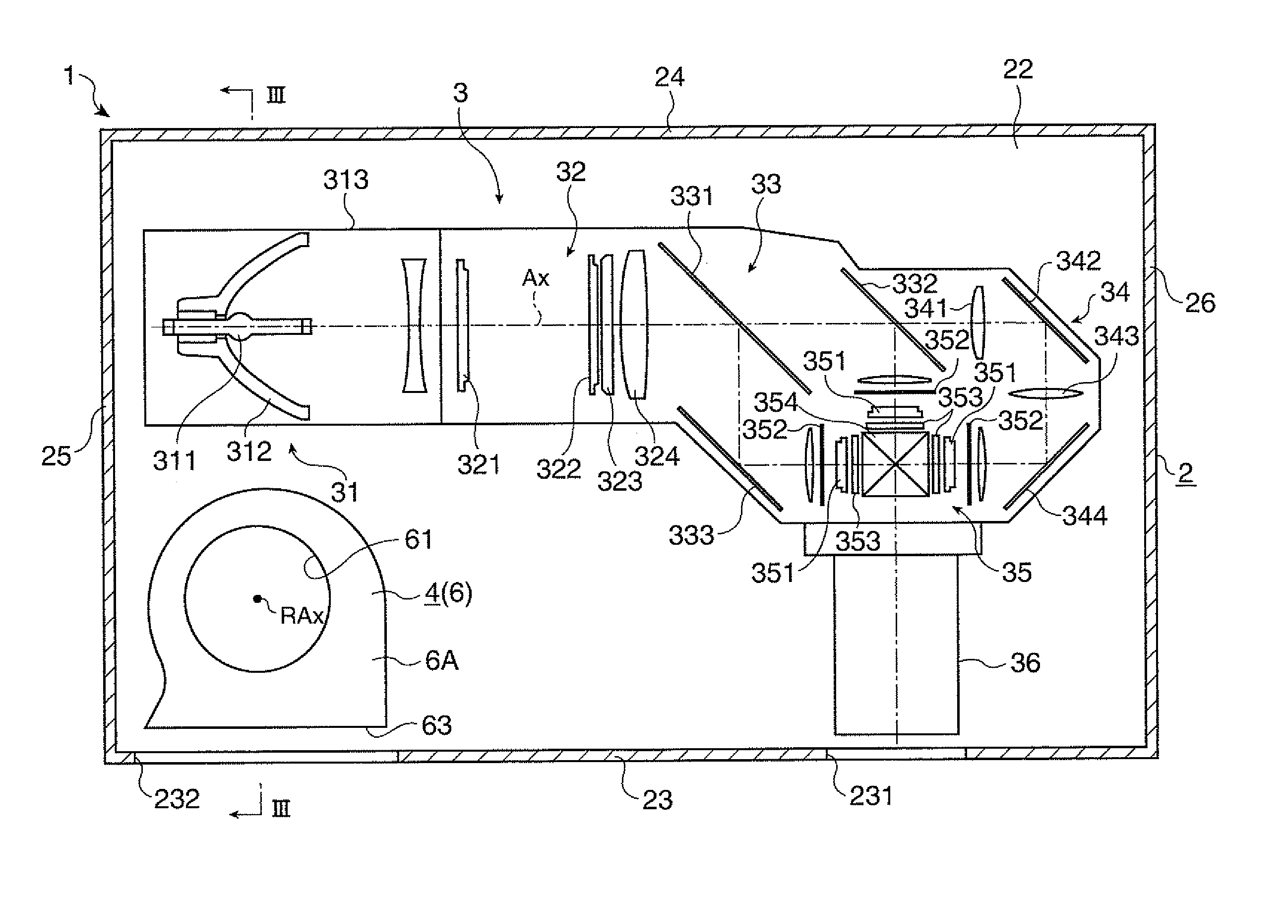
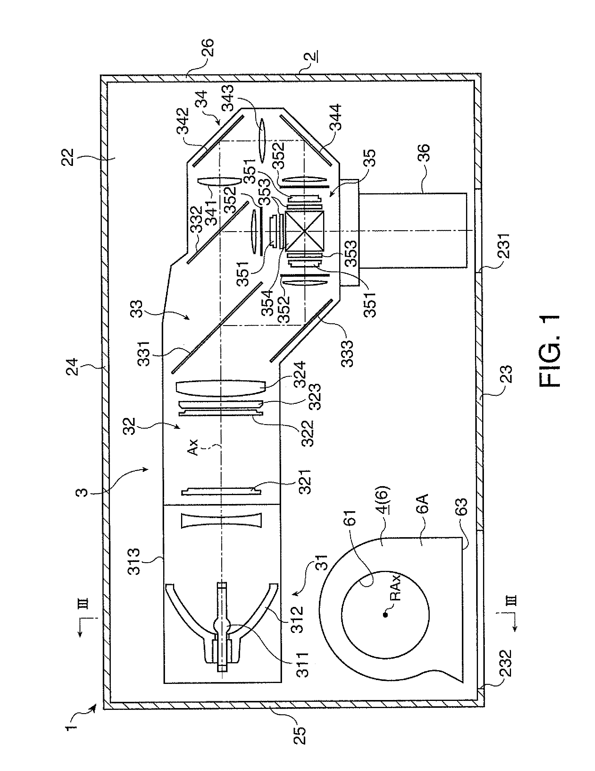
[0038]FIG. 1 schematically illustrates the internal structure of a projector 1 according to this embodiment. More specifically, FIG. 1 shows the internal structure of the projector 1 as viewed from a top surface 21.

[0039]In the following description, the side on which a projection lens 36 described later is disposed corresponds to the “front surface” side, and the side opposite to the front surface side corresponds to the “rear surface” side for convenience of explanation.

[0040]A “vertical axis” in the following description refers to the direction in which the weight of the projector 1 is applied when the projector 1 is placed on an installation surface such as a desk (direction crossing the sheet surface of FIG. 1 at right angles).

[0041]The projector 1 modulates light according to image information and projects the light on a screen (not shown). As ...


PUM


Abstract

A projector includes: an external housing; and an exhaust fan configured to suck an air within the external housing and discharges the sucked air to the outside, the external housing has a top and bottom surface crossing a vertical axis, an air discharge port through that the air discharged from the exhaust fan is discharged to the outside, and a side surface that connects the top surface and the bottom surface, the exhaust fan constituted by a turbo fan that has an impeller rotatable around a predetermined rotation axis, and the rotation axis extends along the vertical axis.

Description

CROSS-REFERENCE[0001]The entire disclosure of Japanese Patent Application No. 2010-075017 filed Mar. 29, 2010 is expressly incorporated by reference herein.BACKGROUND[0002]1. Technical Field[0003]The present invention relates to a projector.[0004]2. Related Art[0005]A projector which prevents temperature increase within its external housing by discharging air from the inside of the external housing to the outside by the function of an exhaust mechanism having a cooling fan is known (for example, see JP-A-2005-242156).[0006]The exhaust mechanism disclosed in JP-A-2005-242156 includes a cooling fan constituted by a so-called axial fan whose air intake direction and discharge direction extend along the rotation axis of the fan. The axial fan is provided in such a condition that the rotation axis of the fan extends along the horizontal axis within the external housing (along the top surface or the bottom surface crossing the vertical axis of the external housing).[0007]According to the ...

Claims


Application Information

Patent Timeline
Patent Type & Authority Patents(United States)
IPC IPC(8): G03B21/18
CPCG03B21/16
Inventor NAGUMO, TOSHIHIKOTAKASUKA, HIDEKI
Owner SEIKO EPSON CORP
Why Eureka
Try Eureka