Atomic layer deposition for controlling vertical film growth

a technology of atomic layer and vertical film growth, which is applied in the direction of solid-state diffusion coating, plasma technique, vacuum evaporation coating, etc., can solve the problems of excessive film deposited on top of narrow-pitch pattern, inability to use direction-selective film growth technology, etc., and achieve selective film growth rate in longitudinal direction virtually reduced

Active Publication Date: 2013-11-26
ASM JAPAN
View PDF8 Cites 402 Cited by
  • Summary
  • Abstract
  • Description
  • Claims
  • Application Information

AI Technical Summary

Benefits of technology

[0023]If this transverse ALD is applied to a gap filling, the film growth can be suppressed in the same longitudinal direction in all trenches even when both shallow trenches (narrow trenches) and wide-pitch trenches are buried on a flat surface, which allows for suppression of film deposition or virtually non-deposition of film even on top of shallow trenches. In other words, the film growth rate in a longitudinal direction can be selectively and virtually reduced with respect to the film growth ratio in a transverse direction. As a result, CMP or dry etching in a subsequent process can be reduced or eliminated.

Problems solved by technology

If this ALD is applied to a gap filling, side wall spacer or spacer-defined double patterning (SDDP), however, the 100% step coverage will present problems, although such application is very effective in terms of film quality and in-plane uniformity.
ALD will present the above problems when patterns of different pitches are buried uniformly.
If wide-pitch patterns are buried by means of ALD until their surface becomes flat, excessive film will deposit on top of narrow-pitch patterns.
As for PE-CVD, a technology for film growth in a selected direction, which is called “Flowable CVD,” is available, but no such direction-selective film growth technology is available in the case of ALD.
In all of the aforesaid embodiments, any element used in an embodiment can interchangeably or additionally be used in another embodiment unless such a replacement is not feasible or causes adverse effect.

Method used


Image

  • Atomic layer deposition for controlling vertical film growth
  • Atomic layer deposition for controlling vertical film growth
  • Atomic layer deposition for controlling vertical film growth

Examples


Embodiment Construction

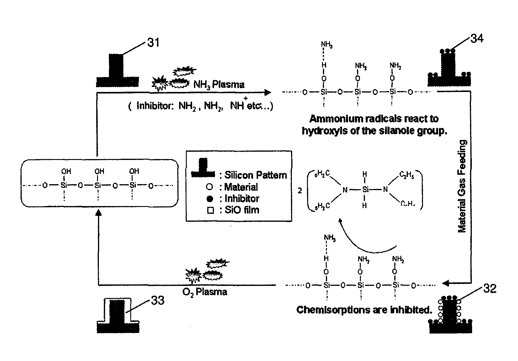
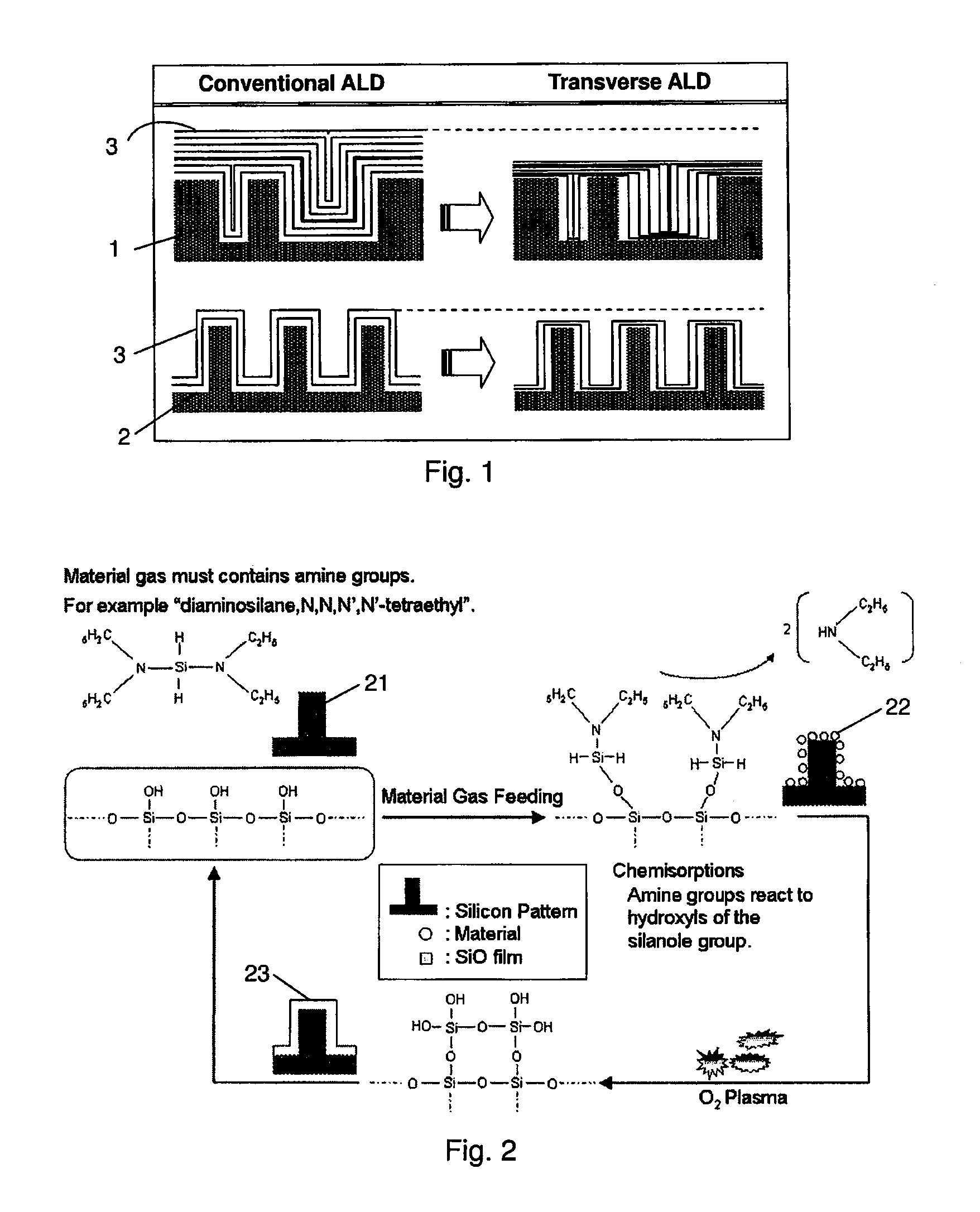
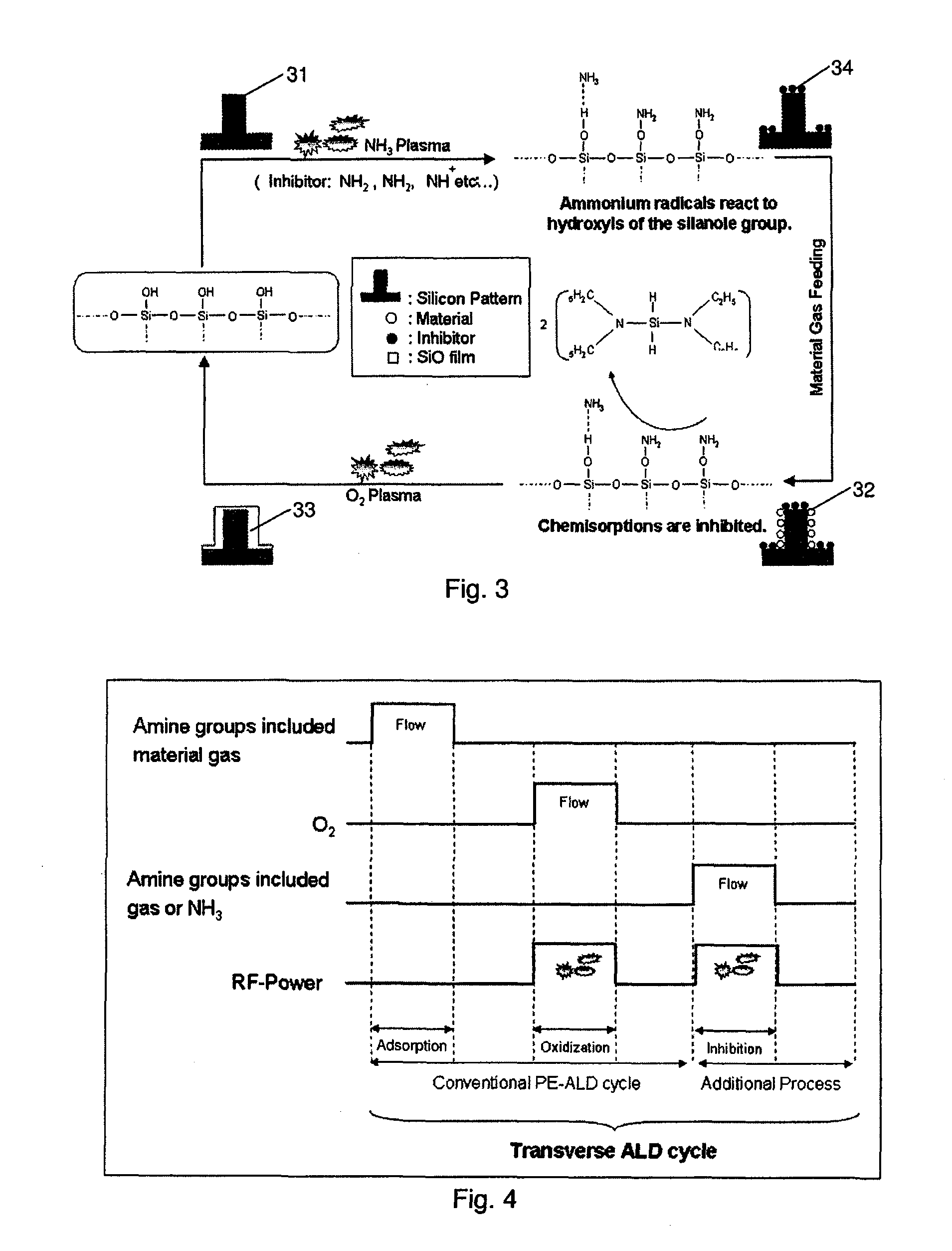
[0038]In this disclosure, a “vertical direction”, “horizontal direction”, “height direction”, “thickness direction”, “transverse direction”, etc. refer to a direction generally or substantially in that direction, and these directions are relative to a reference direction. In this disclosure, “gas” may include vaporized solid and / or liquid and may be constituted by a mixture of gases. In this disclosure, the precursor gas, the oxidizing gas, the inhibitor gas, and the additive gas (inert gas, rare gas, carrier gas, seal gas, or other nonreactive gas) may be different from each other or mutually exclusive in terms of gas types, i.e., there is no overlap of gas types among these categories. Gases can be supplied in sequence with or without overlap. Further, in this disclosure, any two numbers of a variable can constitute an applicable range of the variable, and any ranges indicated may include or exclude the endpoints. A “film” may refer to a layer continuously extending in a direction...


PUM

PropertyMeasurementUnit
frequencyaaaaaaaaaa
thicknessaaaaaaaaaa
distanceaaaaaaaaaa

Abstract

A method for forming a film by atomic layer deposition wherein vertical growth of a film is controlled, includes: (i) adsorbing a metal-containing precursor for film formation on a concave or convex surface pattern of a substrate; (ii) oxidizing the adsorbed precursor to form a metal oxide sub-layer; (iii) adsorbing a metal-free inhibitor on the metal oxide sub-layer more on a top / bottom portion than on side walls of the concave or convex surface pattern; and (iv) repeating steps (i) to (iii) to form a film constituted by multiple metal oxide sub-layers while controlling vertical growth of the film by step (iii). The adsorption of the inhibitor is antagonistic to next adsorption of the precursor on the metal oxide sub-layer.

Description

BACKGROUND[0001]1. Field of the Invention[0002]The present invention generally relates to atomic layer deposition (ALD) technology, particularly to a method for forming a film by ALD which controls film growth in a vertical direction.[0003]2. Description of the Related Art[0004]Basically, Atomic Layer Deposition (ALD) is implemented by repeating a process of oxidizing, by means of plasma decomposition reaction or thermal reaction in an oxygen atmosphere, a material adsorbed onto a substrate. This ALD is largely classified into two types based on the oxidization method. To be specific, the type of ALD that uses plasma decomposition reaction of oxygen is called “Plasma Enhanced ALD (PE-ALD),” while the other type of ALD that uses thermal reaction in an oxygen ambience is called “Thermal ALD.”[0005]In ALD, a film grows more gradually than when PE-CVD is used. However, ALD is characterized in that, because the material which has been adsorbed onto the substrate as an atomic layer is oxi...

Claims


Application Information

Patent Timeline
Patent Type & Authority Patents(United States)
IPC IPC(8): H05H1/24B05D1/36B05D3/00B05D1/32B05D5/00
CPCC23C16/04C23C16/40C23C16/45534C23C16/45542C23C16/401C23C16/505
Inventor UEDA, SHINTARO
Owner ASM JAPAN
Why Eureka
Try Eureka