Surge arrester

a surge arrester and resistor technology, applied in the direction of overvoltage protection resistors, emergency protective arrangements for limiting excess voltage/current, and arrangements responsive to excess voltage, can solve the problems of surge arresters being susceptible to gas formation inside the active part of the active part under overload of the diverting element, and contributing to the failure of surge arresters

Active Publication Date: 2013-11-26
HITACHI ENERGY SWITZERLAND AG
View PDF13 Cites 7 Cited by
  • Summary
  • Abstract
  • Description
  • Claims
  • Application Information

AI Technical Summary

Benefits of technology

[0030]According to an exemplary embodiment of the present disclosure, the connecting element has a homogeneous structure and a homogeneous material structure. This structure of the connecting element enables it to be manufactured completely by means of an injection molding method. In consequence, the surge arrester can be manufactured extremely cost-effectively since it can be produced largely completely automatically.

Problems solved by technology

However, in this known surge arrester, a gap is formed between the frame and the varistor block.
Such accumulations of water can contribute to the failure of the surge arrester.
However, known surge arresters are susceptible to gas formation inside the active part under overload of the diverting element, that is to say if the active part with the varistor has absorbed too much energy due to too high a temporary overvoltage or too high a line discharge.
If the gas cannot escape from the surge arrester, this leads to an explosion of the surge arrester.
This represents a danger for the plant itself in which the surge arrester is arranged and for persons who are occupied in the immediate vicinity of the surge arrester.

Method used


Image

  • Surge arrester
  • Surge arrester
  • Surge arrester

Examples


Embodiment Construction

[0025]Exemplary embodiments of the present disclosure provide an arrester which can be manufactured cost-effectively, is reliable in operation and meets the specifications of the relevant safety standards.

[0026]Exemplary embodiments of the present disclosure provide a surge arrester, a modularly constructed arrester system, a method for producing a surge arrester.

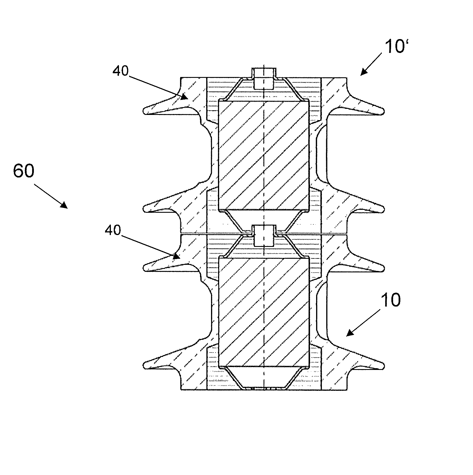
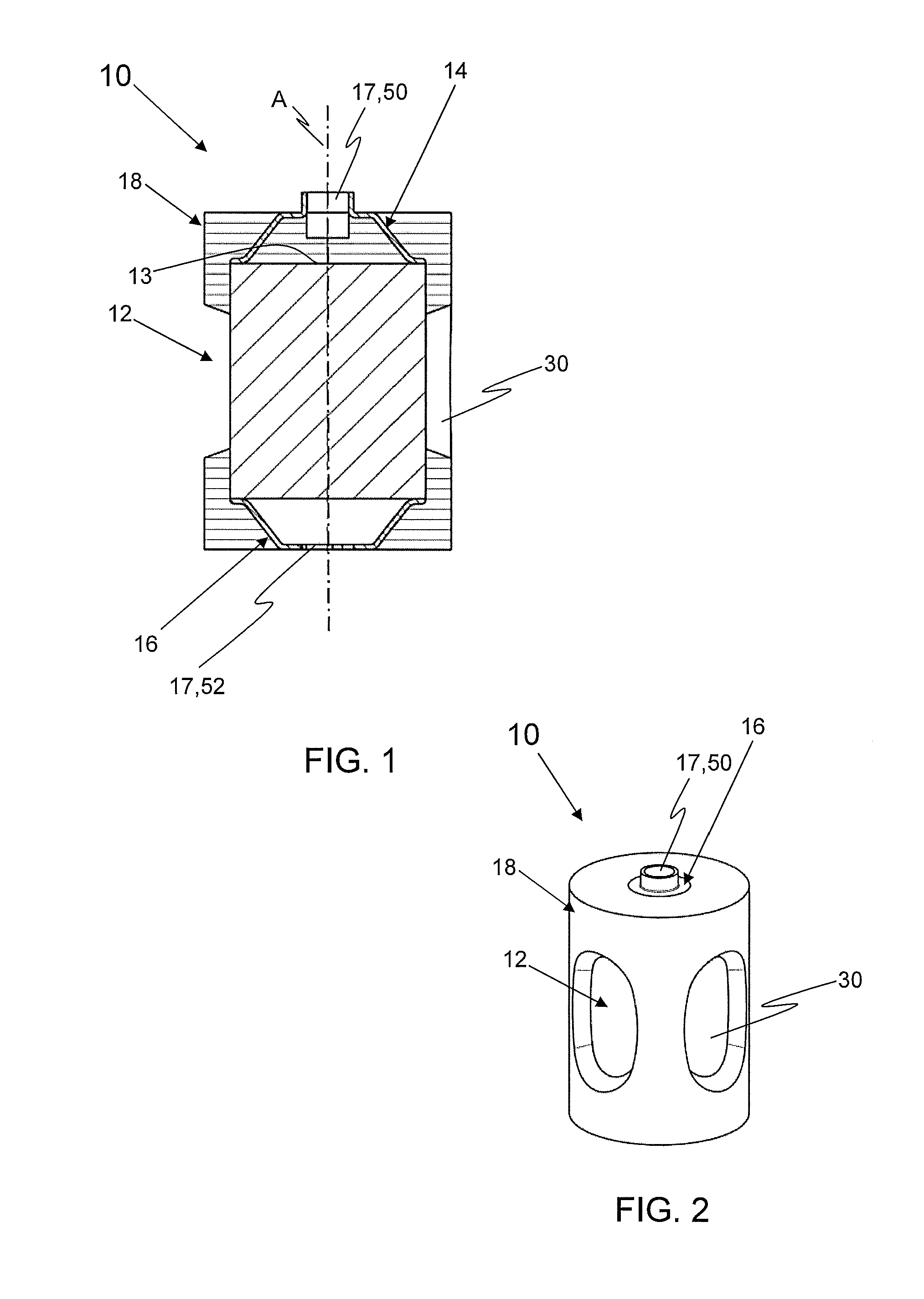
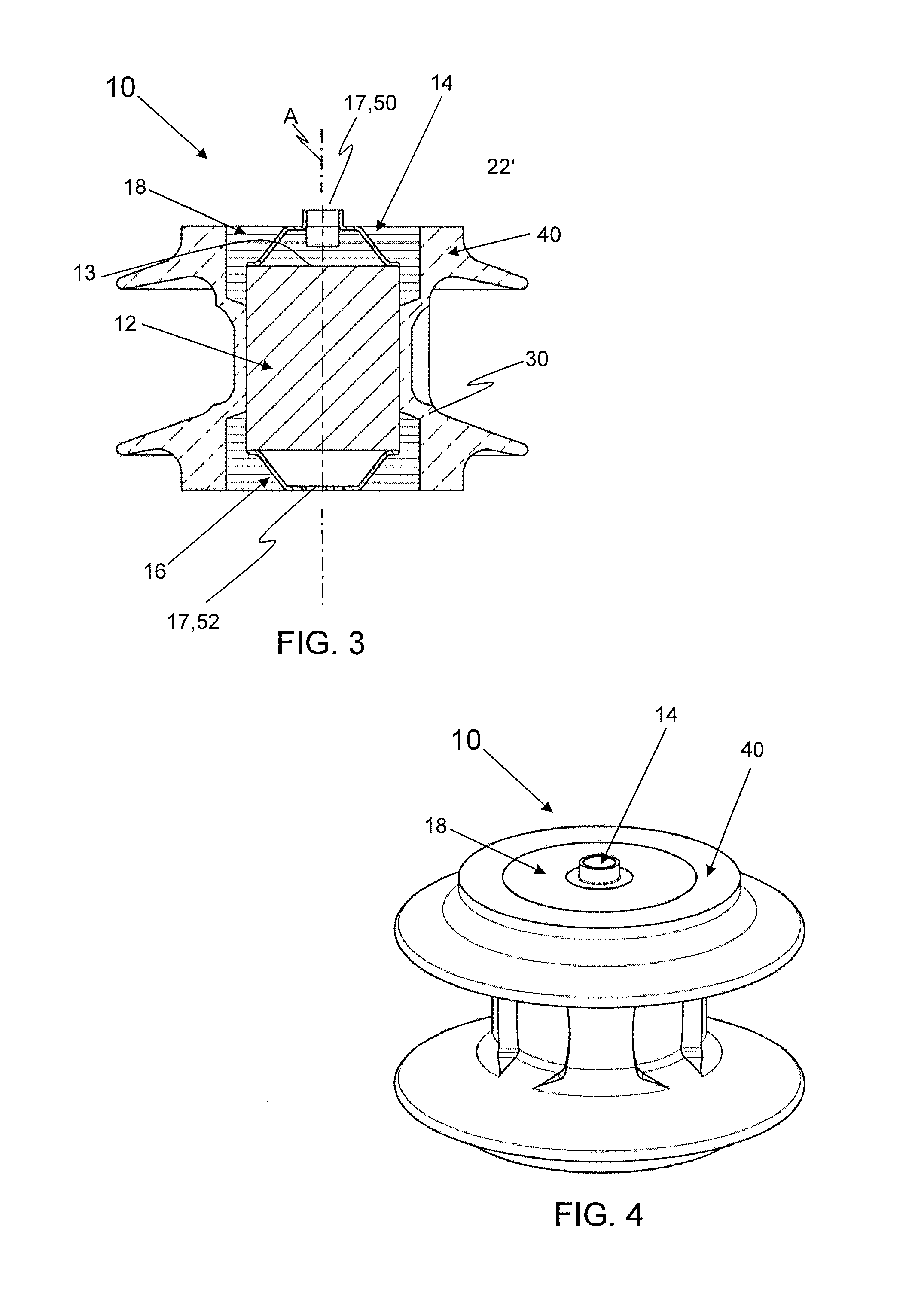
[0027]In accordance with an exemplary embodiment, a surge arrester according to the present disclosure includes an active part, two electrodes resting against the active part, and a connecting element of an insulating material in which the active part and the electrodes are arranged. According to an exemplary embodiment of the present disclosure, the connecting element shrinks during its production. Due to the shrinkage of the connecting element during the cooling and / or curing, the electrodes are firmly pressed against the active part which produces good electrical contact between the respective electrode and the active pa...


PUM

PropertyMeasurementUnit
voltageaaaaaaaaaa
thicknessaaaaaaaaaa
thicknessaaaaaaaaaa

Abstract

A surge arrester includes an active part, two electrodes resting against the active part and a connecting element. The active part and the electrodes are arranged in the connecting element. The connecting element is produced in an injection molding method or die-casting method, in which the connecting element shrinks during its production. As a result, the electrodes are firmly pressed against the active part.

Description

RELATED APPLICATION(S)[0001]This application is a continuation of International Application No. PCT / EP2011 / 051655 filed on Feb. 4, 2011 which claims priority under 35 U.S.C. §119 to European Patent Application No. 10152777.8 filed in Europe on Feb. 5, 2010, the entire contents of which are hereby incorporated by reference in their entirety.FIELD[0002]The present disclosure relates to the field of surge arresters. More particularly, the present disclosure relates to a modularly constructed arrester system and to a method for producing the surge arrester.BACKGROUND INFORMATION[0003]Surge arresters are known in the most varied embodiments. For example, EP-A-0 642 141 discloses a surge arrester. This known surge arrester has an active part for diverting overvoltage which, in particular, consists of varistor blocks. The active part or the varistor blocks, respectively, are inserted into a prefabricated frame of fiber-glass reinforced polyamide. The known frame has on its sides frame open...

Claims


Application Information

Patent Timeline
Patent Type & Authority Patents(United States)
IPC IPC(8): H02H1/00
CPCH01C7/12Y10T29/49117
Inventor GEBHARDT, LUTZEGGER, DANIELNEESER, DANIELSCHON, DIETER
Owner HITACHI ENERGY SWITZERLAND AG
Why Eureka
Try Eureka