Hybrid echo and noise suppression method and device in a multi-channel audio signal

a multi-channel audio signal and hybrid echo technology, applied in the direction of substation equipment, two-way loud-speaking telephone systems, interconnection arrangements, etc., can solve the problems of insufficient removal of echo, insufficient estimation of the spectral envelope of the echo signal, and insufficient adjustment of the adaptive filter predicting the spectral envelop

Inactive Publication Date: 2013-11-26
ECOLE POLYTECHNIQUE FEDERALE DE LAUSANNE (EPFL)
View PDF17 Cites 20 Cited by
  • Summary
  • Abstract
  • Description
  • Claims
  • Application Information

AI Technical Summary

Problems solved by technology

The problem with this technique is that the adaptive filters predicting the spectral envelopes need to re-converge every time when the properties of the loudspeaker signal change.
This signal dependence of the adaptive filters results in the problem that often the echo signal spectral envelope is not estimated precisely enough and the echo is not sufficiently removed.

Method used


Image

  • Hybrid echo and noise suppression method and device in a multi-channel audio signal
  • Hybrid echo and noise suppression method and device in a multi-channel audio signal
  • Hybrid echo and noise suppression method and device in a multi-channel audio signal

Examples


Embodiment Construction

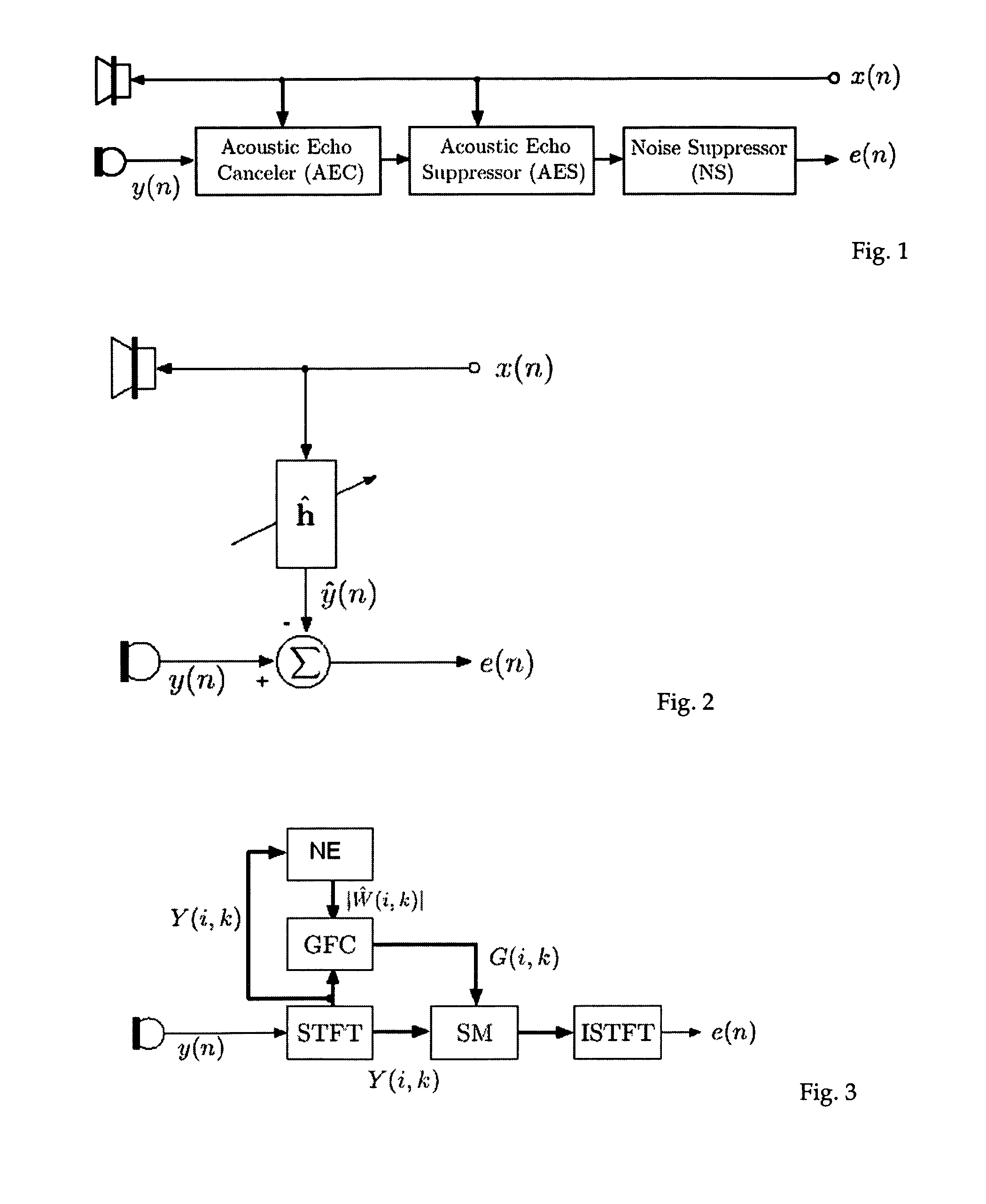
[0029]FIG. 1 illustrates a handsfree speech communication client system with an AEC, AES, and NS. The microphone signal is first processed in the Acoustic Echo Canceller (AEC), then passed to the Acoustic Echo Suppressor (AES) and finally transmitted to a Noise Suppressor (NS). It is to be noted that both AEC and AES need information from the loudspeaker signal.

[0030]FIG. 2 shows a general view of an adaptive echo canceller. The echo estimate ĥ estimated from the loudspeaker signal x(n) is subtracted from the microphone signal y(n) to produce echo free microphone signal e(n).

Noise Suppressor (NS)

[0031]FIG. 3 illustrates a noise suppressor (NS) based on spectral modification. Note that bold lines in the figures denote a plurality of spectral coefficients or subbands. This is a block diagram of a noise suppression algorithm by modifying the spectral magnitude, where STFT, NE, GFC, SM, and ISTFT stand for short-time Fourier transform (STFT), noise estimation (NE), gain filter computati...


PUM


Abstract

Acoustic echo control and noise suppression in telecommunication systems. The proposed method of processing multi-channels audio loudspeakers signals and at least one microphone signal, comprises the steps of: transforming the input microphone signals (y1 (n), y2 (n), . . . , yM (n)) into input microphone short-time spectra, computing a combined loudspeaker signal short-time spectrum [X(i,k)] from the loudspeaker signals, (x1 (n), x2 (n), . . . , xL (n)), computing a combined microphone signal short-time spectrum [Y(i,k)] from the input microphone signal, (y1 (n), y2 (n), . . . , yM (n)), estimating a magnitude or power spectrum of the echo in the combined microphone signal short-time spectrum, computing a gain filter (G(i,k)) for magnitude modification of the input microphone short-time spectra, applying the gain filter to at least one of the input microphone spectra, converting the filtered input microphone spectra into the time domain (e1 (n), e2 (n), . . . , eM (n)).

Description

INTRODUCTION[0001]Acoustic echo control is a necessary component for a full-duplex hands-free telecommunication system to eliminate undesired echo signals that result from acoustic coupling between a loudspeaker and a microphone. If an acoustic echo canceller (AEC) is used, usually also an acoustic echo suppressor (AES) is used (in series after the AEC) to remove residual echoes which occur due to the constantly changing echo paths or when sudden echo path changes occur. Also, often a noise suppressor (NS) is applied for removing stationary noise from the microphone signal.[0002]Recently, systems have been proposed which do not employ an AEC, but do all echo removal using an AES [1, 2]. However, these systems have still high complexity [1], do not efficiently address NS within their core, and are not [2] or only inefficiently [1] applicable for stereo and multi-channel echo control.[0003]We are proposing schemes for AES and NS which have low complexity, high robustness, and are scal...

Claims


Application Information

Patent Timeline
Patent Type & Authority Patents(United States)
IPC IPC(8): H04M9/08H04M9/00H04M1/00
CPCH03G9/005H04M9/082
Inventor FALLER, CHRISTOF
Owner ECOLE POLYTECHNIQUE FEDERALE DE LAUSANNE (EPFL)
Why Eureka
Try Eureka