
Portable transmitter powered by button battery

a button battery and transmitter technology, applied in the field of portable transmitters, can solve the problems of large battery size, inability to easily downsize, and large size of the case itself, and achieve the effect of enhancing the ease of assembly and shrinking the size of the transmitter

Inactive Publication Date: 2013-11-26
DENSO CORP
View PDF16 Cites 6 Cited by
  • Summary
  • Abstract
  • Description
  • Claims
  • Application Information

AI Technical Summary

Benefits of technology

The patent text describes a portable transmitter that is smaller in size and easier to assemble. It achieves this by using a small size button battery and eliminating the need for a battery frame, which results in wasted space and degraded radio waves propagation. The antenna is placed on a region outside the battery to avoid interference with the battery. The case shape is circular, which minimizes unnecessary space usage. Overall, the portable transmitter is more efficient, compact, and has improved radio waves propagation.

Problems solved by technology

Therefore, it is considered that a problem arises in the assembly step to manufacture this structure.
Moreover, the battery frame needs to occupy a space in the structure.
Hence, it is considered that downsizing cannot be performed easily.
Hence, to expand the life of the battery, a large size battery is necessary, however, the larger the size of the battery, the larger the size of the case itself.

Method used


Image

  • Portable transmitter powered by button battery
  • Portable transmitter powered by button battery
  • Portable transmitter powered by button battery

Examples


first embodiment

[0030](First Embodiment)

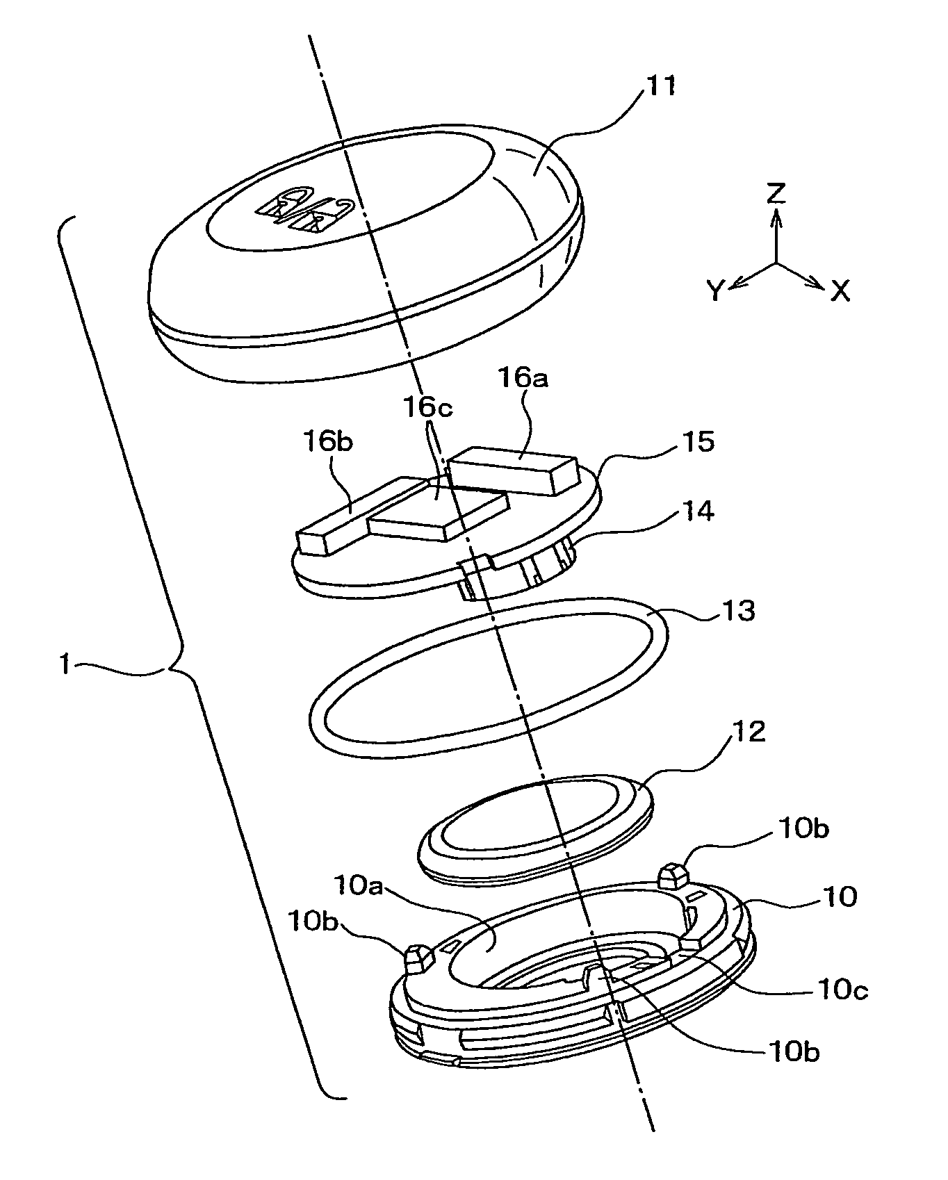
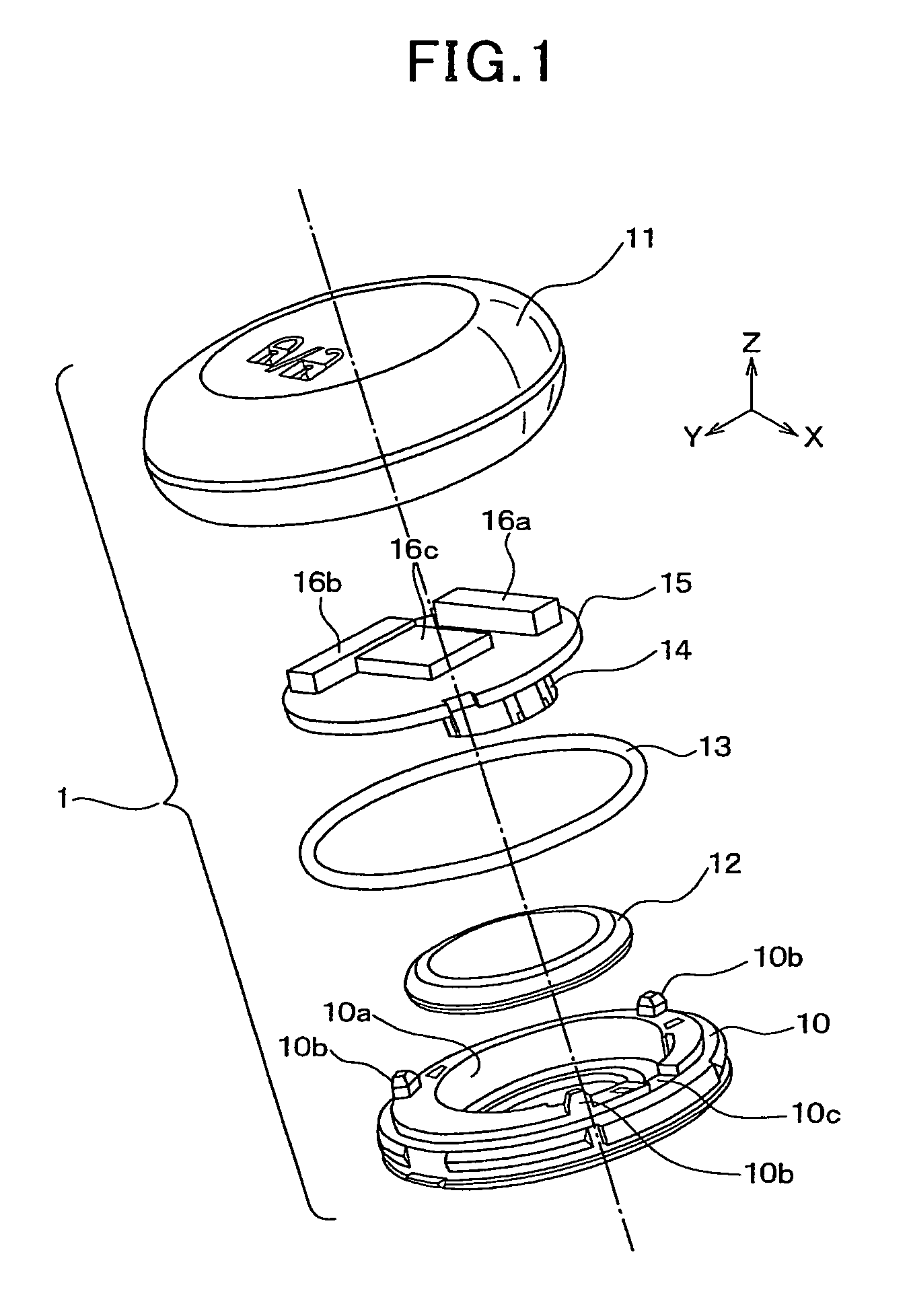
[0031]FIG. 1 is an overall configuration of the portable transmitter according to the first embodiment. The portable transmitter 1 is used for a smart entry system performing opening and closing of the vehicle doors, and starting the engine of the vehicle. The smart entry system is configured to transmit / receive radio waves between the portable transmitter and an on-vehicle equipment (not shown) so as to verify information from the portable transmitter 1.

[0032]The portable transmitter 1 includes a first case member 10, a second case member 11, a button type battery 12 (referred to a battery), an o-ring 13, a terminal 14 and a circuit board 15. In FIG. 1, it is noted that the portable transmitter 1 before assembly is shown. As shown in FIG. 1, Z-axis and a dashed-line indicate a direction in which the above-described parts of the transmitter 1, i.e., case members 10 and 11, the battery 12, o-ring 13, and the circuit board 15 are assembled (laminated).

[0033]The...

second embodiment

[0055](Second Embodiment)

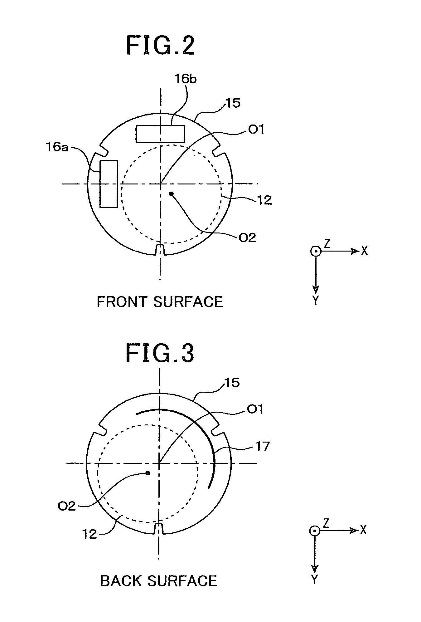
[0056]FIG. 8 illustrates an arrangement of the single axis antennas 16a and 16b, and the pattern-antenna 17 disposed on the circuit board 15 of the portable transmitter 1 according to the embodiment. It is noted that the location of the battery 12 is shown with a dotted line in FIG. 8. Hereinafter is mainly described the portion which differs from the first embodiment. It is noted that the portions identical to the one of the first embodiment are applied with the same reference numbers and the explanation thereof is omitted.

[0057]As shown in FIG. 8, according to the second embodiment, the single axis antenna 16a, 16b and the pattern-antenna 17 are arranged on the surface of the circuit board 15 such that the antennas 16a, 16b and 17 are disposed on a region outside the outer peripheral of the battery 12 (i.e., outer region). According to the second embodiment, the button type battery 12 is arranged such that the center location o2 of the battery 12 and the c...


PUM


Abstract

A portable transmitter includes a circuit board having a button battery and an antenna; and a case accommodating the battery and the circuit board. The case includes first and second case members being engaged with each other. A concave portion is formed on the first or second case members to accommodate the button battery, and a lock portion is formed on the first or second case members to lock the circuit board. While the concave portion accommodates the button battery and the circuit board is locked by the lock portion, a surface of the circuit board and a surface of the button battery are attached, and the first case member and the second case member are engaged.

Description

CROSS REFERENCE TO RELATED APPLICATION[0001]This application is based on and claims the benefit of priority from earlier Japanese Patent Application No. 2010-165975 filed on Jul. 23, 2010 the description of which is incorporated herein by reference.TECHNICAL BACKGROUND[0002]1. Field of the Invention[0003]The present invention relates to a wireless communication unit, and more particularly to a portable transmitter that transmits electromagnetic waves via an antenna of the transmitter powered by a button type battery.[0004]2. Description of the Related Art[0005]Conventionally, a remote key-less system which opens and closes vehicle-doors and starts the engine of the vehicle is known. In the remote key-less system, electromagnetic waves are transmitted / received between user's transmitter device and an on-vehicle unit to verify whether or not the transmitter corresponds to the on-vehicle unit.[0006]In such a remote key-less system, to shrink the size of the transmitter, for example, a ...

Claims


Application Information

Patent Timeline
Patent Type & Authority Patents(United States)
IPC IPC(8): H04B1/034
CPCG07C9/00944H04B1/0346H04B1/034H01Q1/24H05K13/00
Inventor SAITO, TOSHIAKINAKAGAWA, MITSURUSHIMURA, TOKIO
Owner DENSO CORP
Learn More