Optical connector plug

a technology of optical connectors and plugs, applied in the field of optical connector plugs, can solve the problems of difficult to obtain the desired spring force and stroke in the coil spring, the spring cannot be sufficiently biased, and the human body is at risk of having a bad effect, so as to achieve the effect of minimizing the entire length

Active Publication Date: 2013-12-03
SEIKOH GIKEN
View PDF5 Cites 14 Cited by
  • Summary
  • Abstract
  • Description
  • Claims
  • Application Information

AI Technical Summary

Benefits of technology

[0022]In another example of the optical connector plug according to the aspect of the present invention, in a state in which the biasing member and the biasing member receiving portion are disposed on the optical fiber cord, assembling work of the optical connector plug can be performed, and the biasing member and the biasing member receiving portion can be inserted into the housing in the last of the assembling work. As a result, an optical connector plug that can dispose the biasing member and the biasing member receiving portion to overlap at the outer side of components such as the stop ring, the caulking ring, and the boot and minimize the entire length can be provided. In the optical non-coupling state of the optical connector plug, the extension state in which the grip member is moved to the rear side of the axial direction of the shutter holding member by the biasing member is maintained. Therefore, inadvertent movement of the grip member from the extension state to the reduction state in the optical non-coupling state can be prevented.

Problems solved by technology

However, if the high-output communication light is emitted from the front ends of the optical fibers and a human body, particularly, a part such as eyes, is exposed to the communication light, there is a high possibility of having a bad affect on the human body.
However, it is difficult to obtain the desired spring force and stroke in the coil spring and the coil spring cannot sufficiently bias the inner barrel (shutter holding member).
The entire length of the optical connector plug needs to be increased to incorporate the coil spring and it is difficult to engage the optical connector plug in the same space as that of the related art.

Method used


Image

  • Optical connector plug
  • Optical connector plug
  • Optical connector plug

Examples


first embodiment

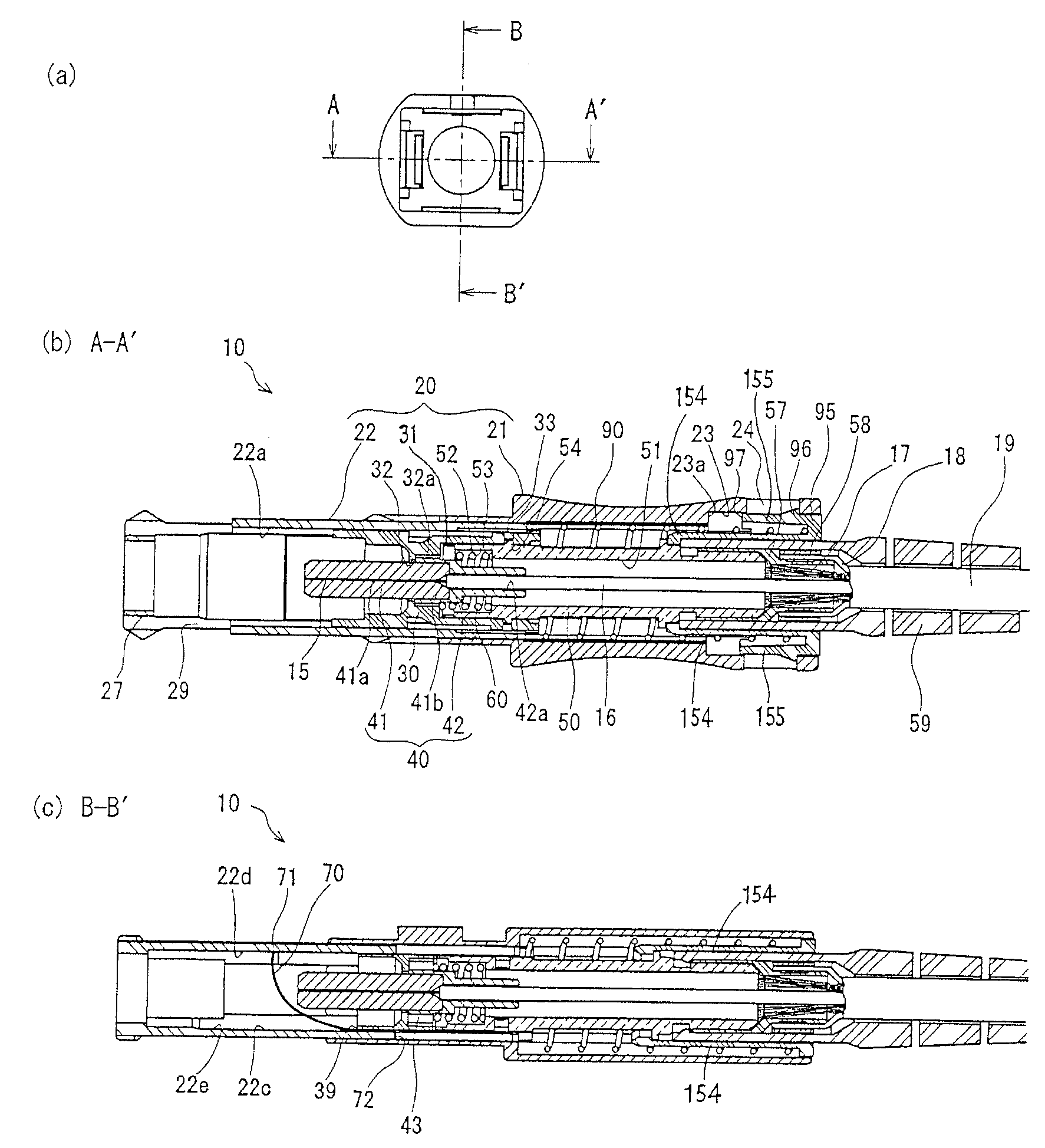
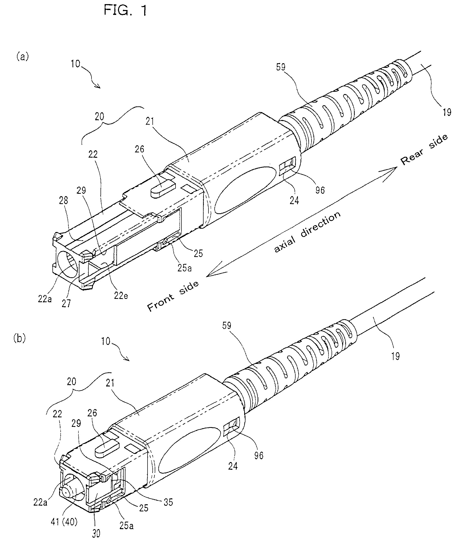
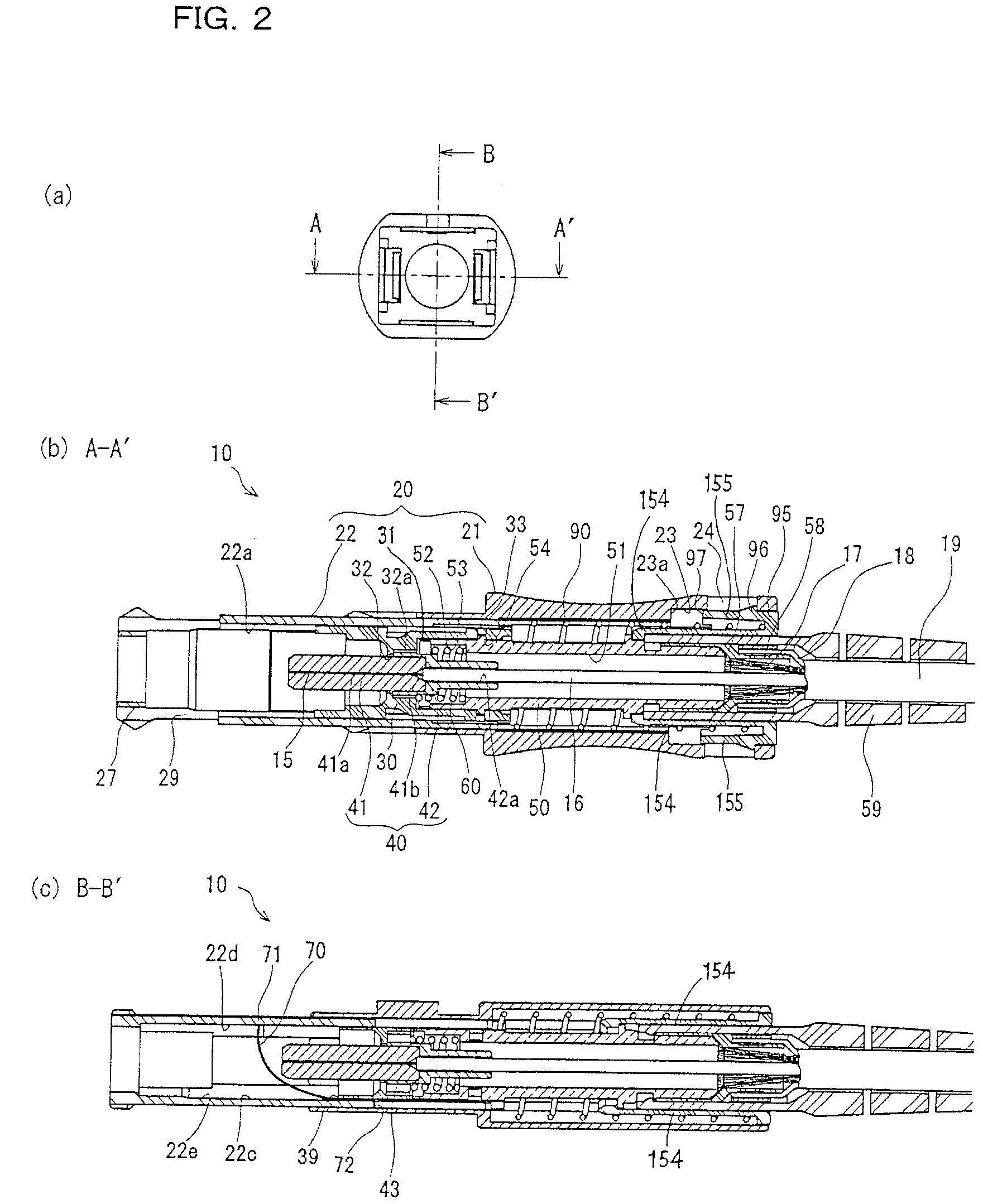
[0034]FIGS. 1A and 1B are perspective views of an optical connector plug 10 according to an embodiment of the present invention and FIGS. 2A to 3C are front views, cross-sectional views taken along the line A-A′, and cross-sectional views taken along the line B-B′ of the optical connector plug 10. FIG. 4 is an exploded perspective view of the optical connector plug 10.

[0035]As illustrated in FIGS. 1A to 4, the optical connector plug 10 according to this embodiment has a shape in which the optical connector plug 10 can be coupled to an SC-type optical connector adaptor to be described below. The optical connector plug 10 includes a housing 20, a plug frame 30 that is held movably in an axial direction (toward the front side and the rear side of an axial direction) in the housing 20, a ferrule 40 that holds an optical fiber 15 for optical coupling and is inserted from the rear of the plug frame 30, a stop ring 50 that has a front end engaged with a rear end of the plug frame 30, and a...


PUM


Abstract

An optical connector plug incorporates a coil spring to bias a shutter holding member to the front side of an axial direction with respect to a plug frame and minimizes the entire length. The plug has a housing that includes a grip member and a shutter holding member that move relatively in the axial direction and the plug frame has an extension state in which the grip member moves to the rear side of the axial direction of the shutter holding member and a reduction state in which the grip member moves to the front side of the axial direction of the shutter holding member. A biasing member that biases the shutter holding member to the front side of the axial direction with respect to the plug frame and a biasing member receiving member that is connected to the plug frame are provided.

Description

BACKGROUND OF THE INVENTION[0001]1. Field of the Invention[0002]The present invention relates to an optical connector plug that holds front ends of optical fibers and couples the optical fibers to each other.[0003]2. Description of the Related Art[0004]In the related art, optical coupling between optical fibers used for optical communication is performed using an optical connector. The optical connector includes optical connector plugs that hold front ends of optical fibers and an optical connector adapter that fix the optical connector plugs to each other and performs optical coupling of the optical fibers.[0005]As the optical connector, an SC-type optical connector (complying with IEC 61754-4) that couples the optical fibers to each other using a ferrule barrel-shaped body (with the outer diameter of 2.5 mm) for holding the optical fibers or a miniaturized MU-type optical connector (complying with IEC 61754-6) using a ferrule barrel-shaped body (with the outer diameter of 1.25 mm)...

Claims


Application Information

Patent Timeline
Patent Type & Authority Patents(United States)
IPC IPC(8): G02B6/36
CPCG02B6/3849G02B6/3825G02B2006/4297G02B6/3893
Inventor TAIRA, JUNJIARAI, NORIMASA
Owner SEIKOH GIKEN
Why Eureka
Try Eureka