Optical network unit with redundant reverse powering from customer premises equipment

a technology of optical network units and reverse powering, applied in the field of communication systems, can solve the problems of high installation and maintenance costs of optical network units (onu) type telecommunication systems, and achieve the effect of ensuring a uniform load sharing

Active Publication Date: 2013-12-03
ADTRAN
View PDF10 Cites 58 Cited by
  • Summary
  • Abstract
  • Description
  • Claims
  • Application Information

AI Technical Summary

Benefits of technology

[0006]In another example, the ONU includes an Ethernet switch connected to the plurality of ports and the power management circuit. A processor is connected to the Ethernet switch and configured to switch power consumption from unused and out-of-service communication ports. The processor in one example is configured to receive a dying gasp interrupt indicative that power is failing on a reverse power supply at a CPE. A manager circuit is configured to receive a signal indicative that the processor receives a dying gasp interrupt and discriminate CPE

Problems solved by technology

Current fiber fed Optical Network Unit (ONU) type telecommunications systems require expensive to

Method used


Image

  • Optical network unit with redundant reverse powering from customer premises equipment
  • Optical network unit with redundant reverse powering from customer premises equipment
  • Optical network unit with redundant reverse powering from customer premises equipment

Examples


Embodiment Construction

[0014]Different embodiments will now be described more fully hereinafter with reference to the accompanying drawings, in which preferred embodiments are shown. Many different forms can be set forth and described embodiments should not be construed as limited to the embodiments set forth herein. Rather, these embodiments are provided so that this disclosure will be thorough and complete, and will fully convey the scope to those skilled in the art.

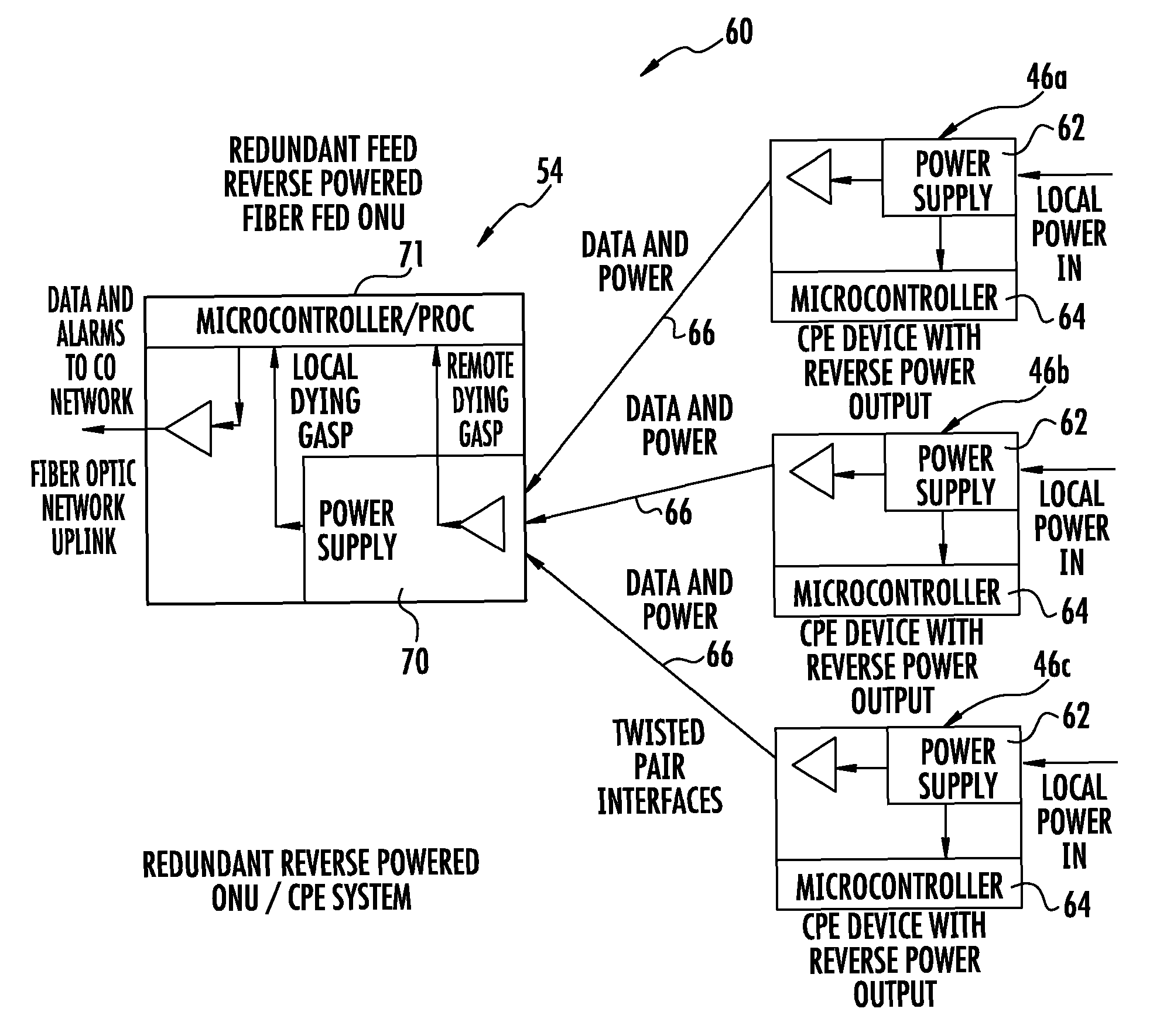
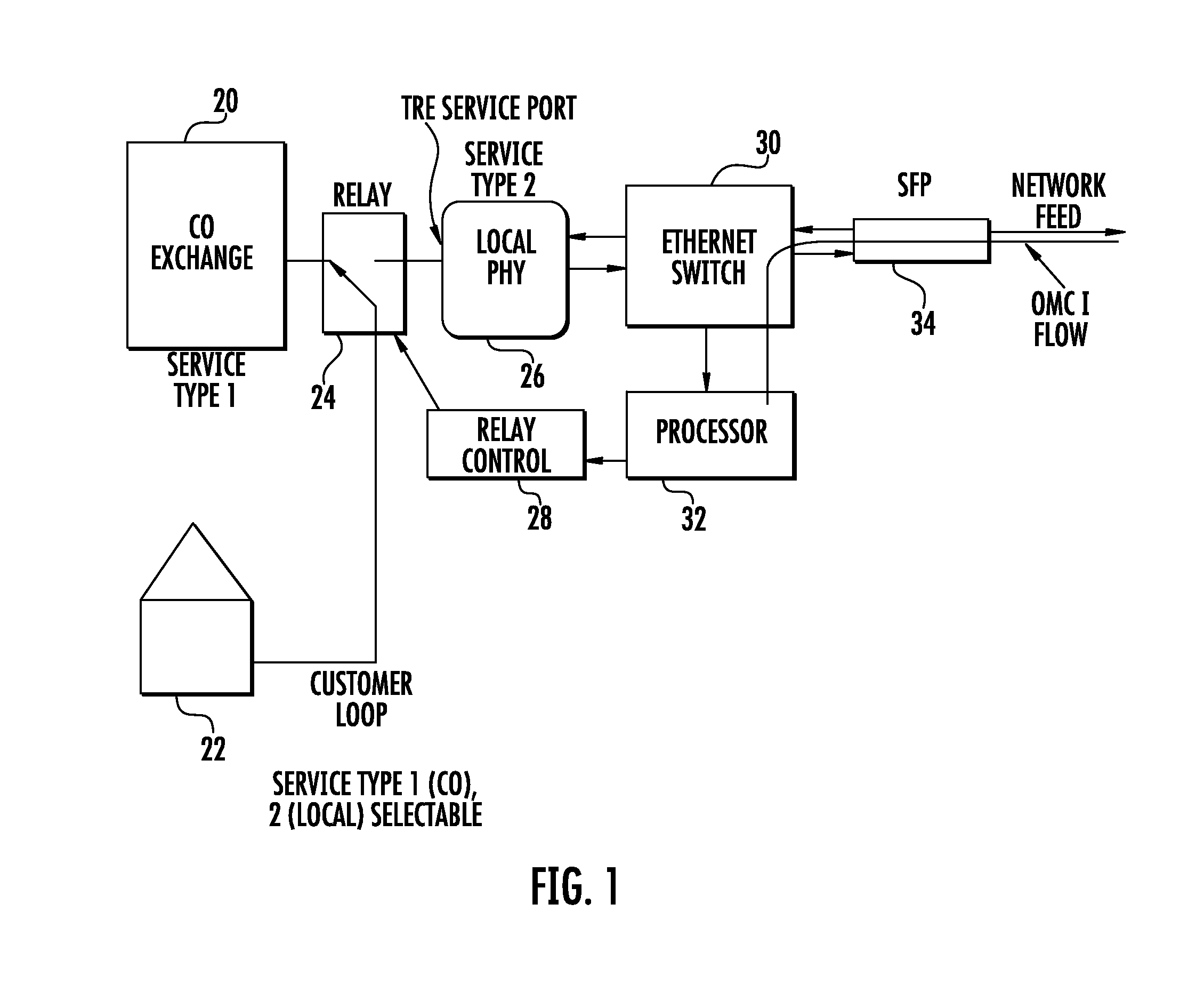
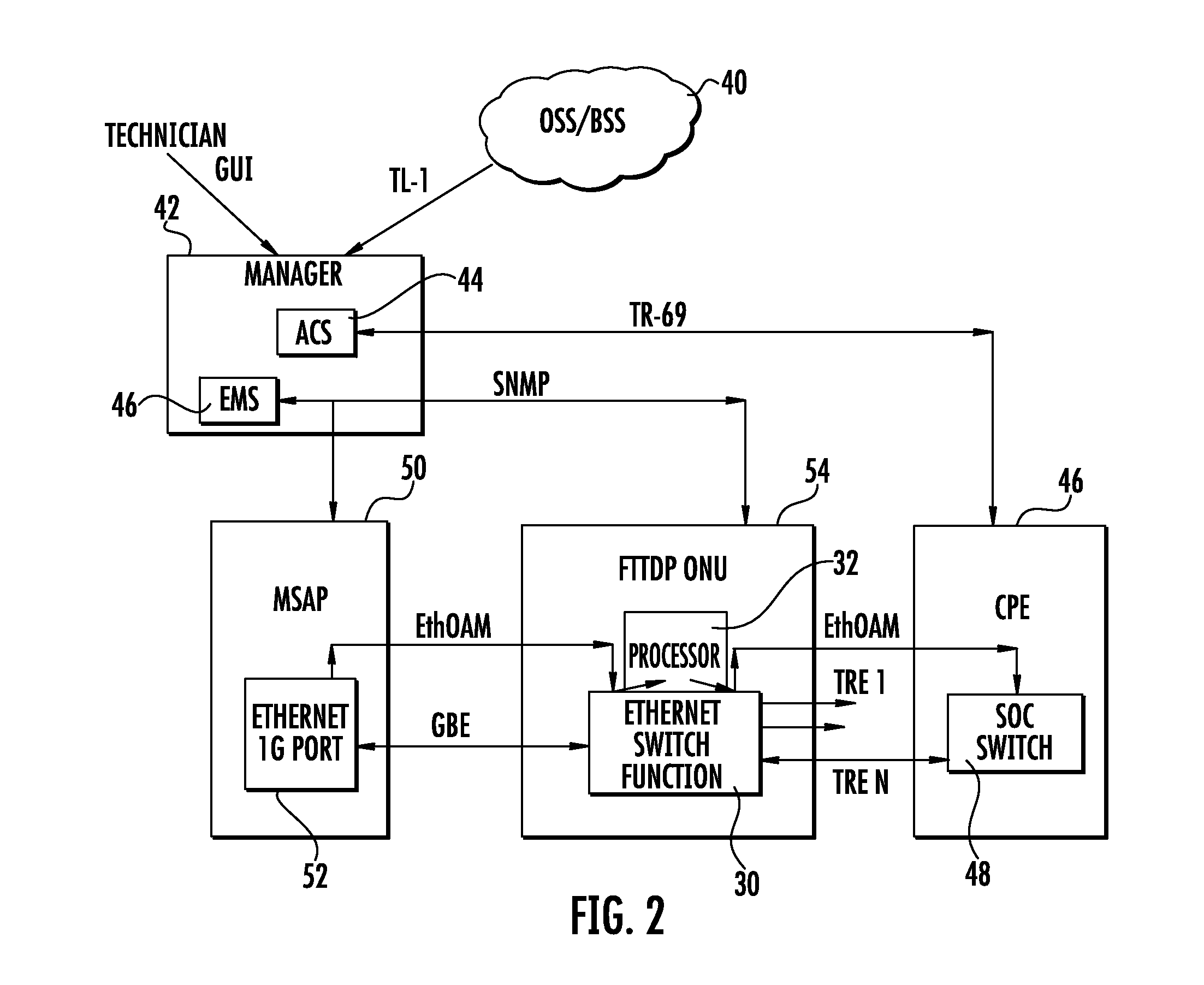
[0015]FIGS. 1 and 2 illustrate basic functional components of a communications system that can incorporate the reverse power system as will be described relative to FIGS. 3-6. FIGS. 1 and 2 are described as an example system that can be used and modified in accordance with a non-limiting example. Although the description relative to FIGS. 1 and 2 are described relative to a remotely managed switching element that resides in the ONU, it should be understood that the reverse powered system is used.

[0016]In accordance with a non-limiting exampl...


PUM


Abstract

In accordance with a non-limiting example, an optical communications system includes a plurality of Customer Premises Equipment (CPE), each having a reverse power supply circuit and each connected to a wire pair and configured to transmit and receive data and provide reverse power over the wire pair. An Optical Network Unit (ONU) includes a plurality of communication boards. A respective communication port is connected to a selected wire pair and its associated CPE through which data is transmitted and received and power received therefrom. A power management circuit is connected to each of the communication ports and configured to receive power and provide power sharing and manage power consumption and power supply redundancy from the plurality of CPE through the communication ports.

Description

FIELD OF THE INVENTION[0001]The present invention relates to communications systems, and more particularly, this invention relates to powering an Optical Network Unit (ONU).BACKGROUND OF THE INVENTION[0002]Current fiber fed Optical Network Unit (ONU) type telecommunications systems require expensive to install and maintain power rectifiers and AC mains meter and service to power the ONU equipment. Power over Ethernet (PoE) provides single port powering over Ethernet service cables. There are yet other systems where a network element receives power and data over electrical lines from a Customer Premises Equipment (CPE). There is a desire, however, for greater management control and redundancy that is not provided by these types of systems.SUMMARY OF THE INVENTION[0003]In accordance with a non-limiting example, an optical communications system includes a plurality of Customer Premises Equipment (CPE), each having a reverse power supply circuit and each connected to a wire pair and con...

Claims


Application Information

Patent Timeline
IPC IPC(8): G06F1/26
CPCH04L12/10H04L12/2885H04L12/2898H04Q2011/0079H04Q11/0067
Inventor SMITHROBINSON, STEVEN M.JOFFE, DANIEL M.
Owner ADTRAN
Why Eureka
Try Eureka