Cooling air supply for the cooling of different systems requiring cooling air in an aircraft

a technology for cooling air supply and aircraft, which is applied in the field of cooling air supply system for aircraft, can solve the problems of weakened aircraft structure, high manufacturing and maintenance costs, and increased aircraft weight, and achieves relatively high additional air resistance (drag)

Active Publication Date: 2013-12-10
AIRBUS OPERATIONS GMBH
View PDF26 Cites 19 Cited by
  • Summary
  • Abstract
  • Description
  • Claims
  • Application Information

AI Technical Summary

Benefits of technology

[0009]In accordance with another development of the invention, a check valve is provided in the diffuser or in one of the second bypass lines leading off from the diffuser, and this blocks cooling air so that it does not flow back into the diffuser. Preferably the first bypass line and the second bypass line are arranged in parallel so that undesired flowing back of cooling air which was sucked in from the aircraft surroundings by the air compressor, can be prevented.

Problems solved by technology

In this way, the individual devices requiring cooling air were supplied with sufficient quantities of cooling air, however this led to sophisticated cooling air supply systems, which all together significantly added to the weight of the aircraft, as well as associated high manufacture and maintenance costs.
Moreover, several air inlets and air outlets had to be provided in the outer skin of the aircraft which weakened the aircraft structure and which led to relatively high additional air resistance (drag) of the aircraft.
Finally, as a result of the different cooling air supply systems, a considerable amount of structural space within the aircraft interior was taken up.

Method used


Image

  • Cooling air supply for the cooling of different systems requiring cooling air in an aircraft
  • Cooling air supply for the cooling of different systems requiring cooling air in an aircraft

Examples


Embodiment Construction

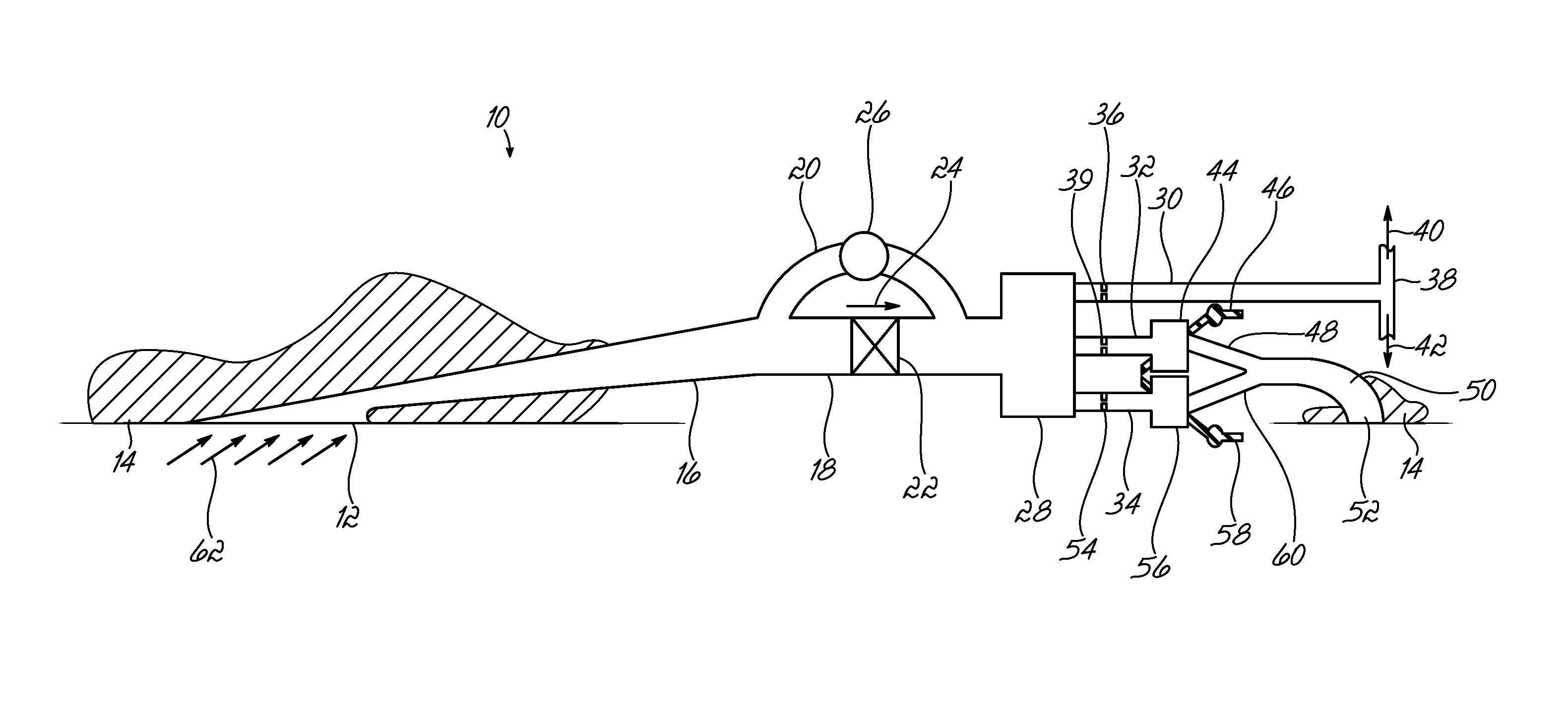
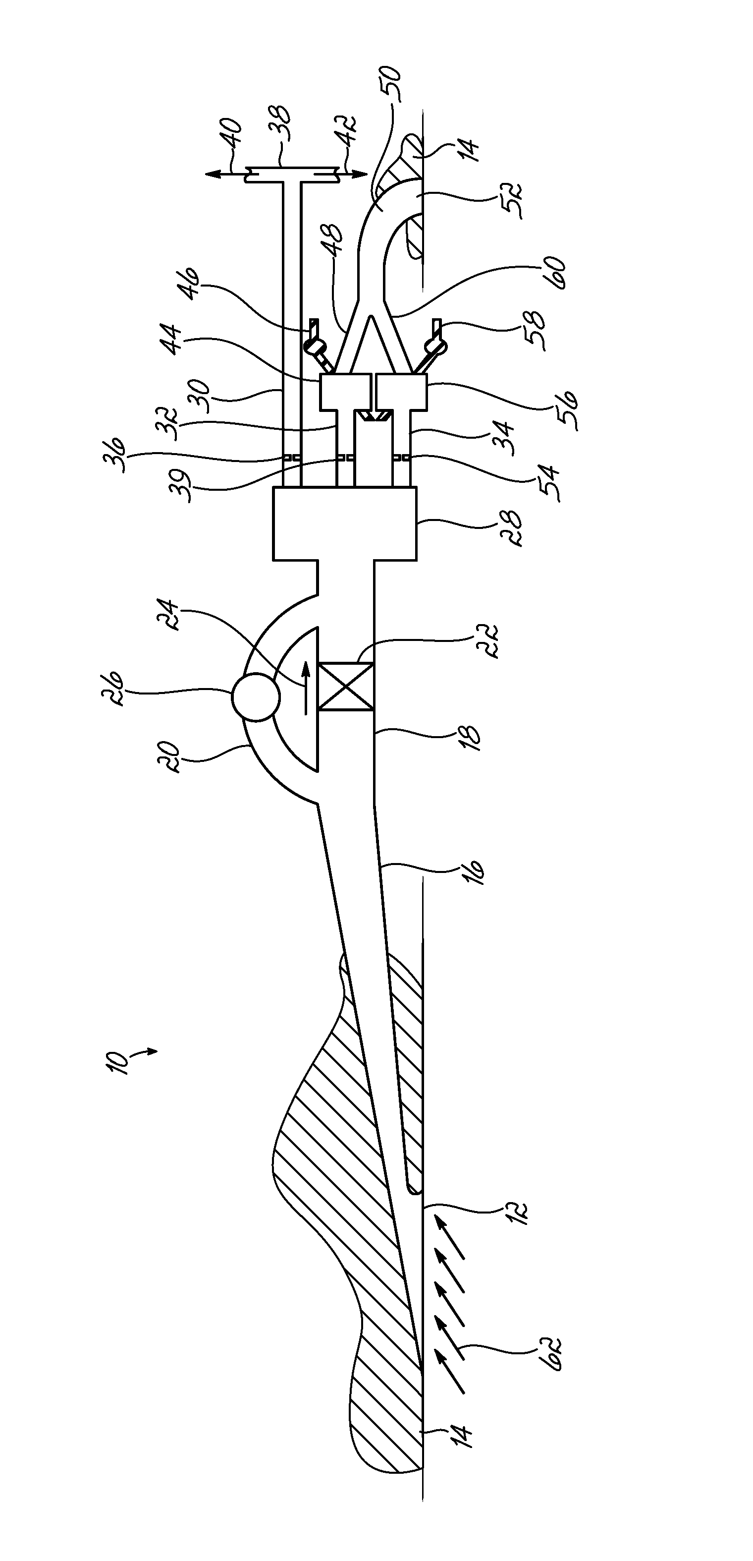
[0015]The cooling air supply system 10 in accordance with the invention includes an NACA air inlet 12 which is positioned in the outer skin of the aircraft 14. The NACA air inlet 12 leads to a diffuser 16, at the end of which is a line section 18 and a bypass channel 20 in the style of a parallel arrangement. In the line section 18 a check valve 22 is positioned, and this permits flow in the direction of the arrow 24, but blocks flow in the opposite direction. A turbo compressor 26 is provided in the bypass channel 20 which, when powered, also causes air to flow in the direction of the arrow 24.

[0016]A cooling air collection chamber 28 joins onto the line section 18. Several cooling air supply lines 30, 32 and 34 lead off of this collection chamber 28 in parallel.

[0017]During flight operations when the aircraft is at cruising altitude, ambient air at a temperature of approx. −50° C. flows into the NACA air inlet 12 in accordance with the arrows 62. The ambient air enters the diffuse...


PUM


Abstract

A cooling air supply system for an aircraft is configured to supply cooling air from the surroundings of the aircraft to at least two devices requiring cooling air (38, 44, 56) within the aircraft. The cooling air supply system includes an air inlet, an air channel communicating with the air inlet, and an air distribution device for the distribution of air from the air channel to the at least two devices requiring cooling air. The air inlet is sized to provide sufficient air flow to accommodate a maximum cooling air requirement of the at least two devices requiring cooling air.

Description

TECHNICAL FIELD[0001]This invention relates to a cooling air supply system for an aircraft which supplies cooling air from the surroundings of an aircraft to at least two devices requiring cooling air within the aircraft.BACKGROUND[0002]In the field of aircraft construction, it is necessary to provide different functional units within the aircraft with cooling air. In the past, in order to meet the different requirements of the devices requiring cooling air within the aircraft, separate cooling air supply systems were provided adapted to each individual device requiring cooling air respectively. In this way, the individual devices requiring cooling air were supplied with sufficient quantities of cooling air, however this led to sophisticated cooling air supply systems, which all together significantly added to the weight of the aircraft, as well as associated high manufacture and maintenance costs. Moreover, several air inlets and air outlets had to be provided in the outer skin of ...

Claims


Application Information

Patent Timeline
Patent Type & Authority Patents(United States)
IPC IPC(8): B60H1/00F25D9/00B64D33/02B64D11/00B64G1/48B64D13/00
CPCB64D13/00Y02T50/44Y02T50/56Y02T50/40Y02T50/50
Inventor SOLNTSEV, ALEXANDERBAMMANN, HOLGER
Owner AIRBUS OPERATIONS GMBH
Why Eureka
Try Eureka