Pixel bit depth conversion in image encoding and decoding

a technology of image encoding and decoding, applied in the field of image encoding apparatus, can solve the problems of increasing the prediction error signal, decreasing the encoding efficiency, and the calculation precision cannot be improved enough

Active Publication Date: 2013-12-10
KK TOSHIBA
View PDF35 Cites 42 Cited by
  • Summary
  • Abstract
  • Description
  • Claims
  • Application Information

AI Technical Summary

Benefits of technology

[0010]It is an object of the present invention to provide an image encoding apparatus and an image encoding method and an image decoding apparatus and an image decoding method to improve an encoding efficiency by enhancing a precision of intra-prediction or motion compensation enough.

Problems solved by technology

Because, in H.264, a rounding error occurs in a process of rounding processing when a prediction signal is generated, it cannot be processed with enough precision in an interpolation filter for intra-prediction or motion compensation, resulting in increasing a prediction error signal and decreasing the encoding efficiency.
However, in JP-A 2003-283872 (KOKAI), enlargement of the dynamic range is done simply within the range of bit precision of the input image, and also calculation precision cannot be improved enough because a rounding error occurs in enlarging the dynamic range.
As a result, the bit depth is shifted by the different number of bits, resulting in occurring mismatch.

Method used


Image

  • Pixel bit depth conversion in image encoding and decoding
  • Pixel bit depth conversion in image encoding and decoding
  • Pixel bit depth conversion in image encoding and decoding

Examples


first embodiment

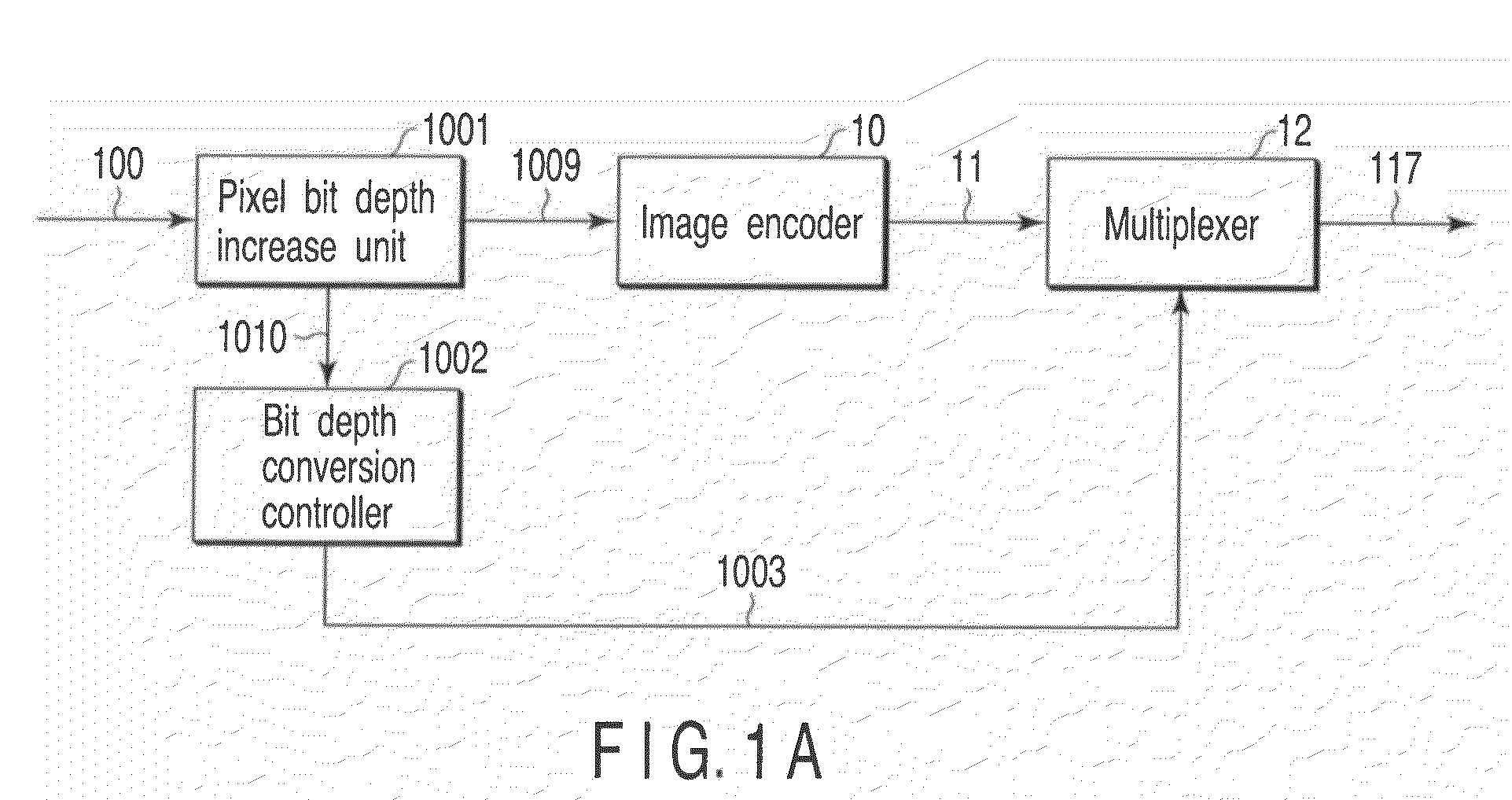
[0077]There will be described a configuration of an image encoding apparatus for video encoding according to the first embodiment referring to FIG. 1A. This image encoding apparatus comprises a pixel bit depth increase unit 1001 to which an input image signal 100 is supplied to increase a pixel bit depth (i.e., a pixel bit depth converter for changing pixel bit depth), an image encoder 10 connected to the output of this pixel bit depth increase unit 1001, a multiplexer 12 connected to the output of this image encoder 10, and a bit depth conversion controller 1002 connected to the other output of the pixel bit depth increase unit 1001 to supply bit depth increase information to the multiplexer 12.

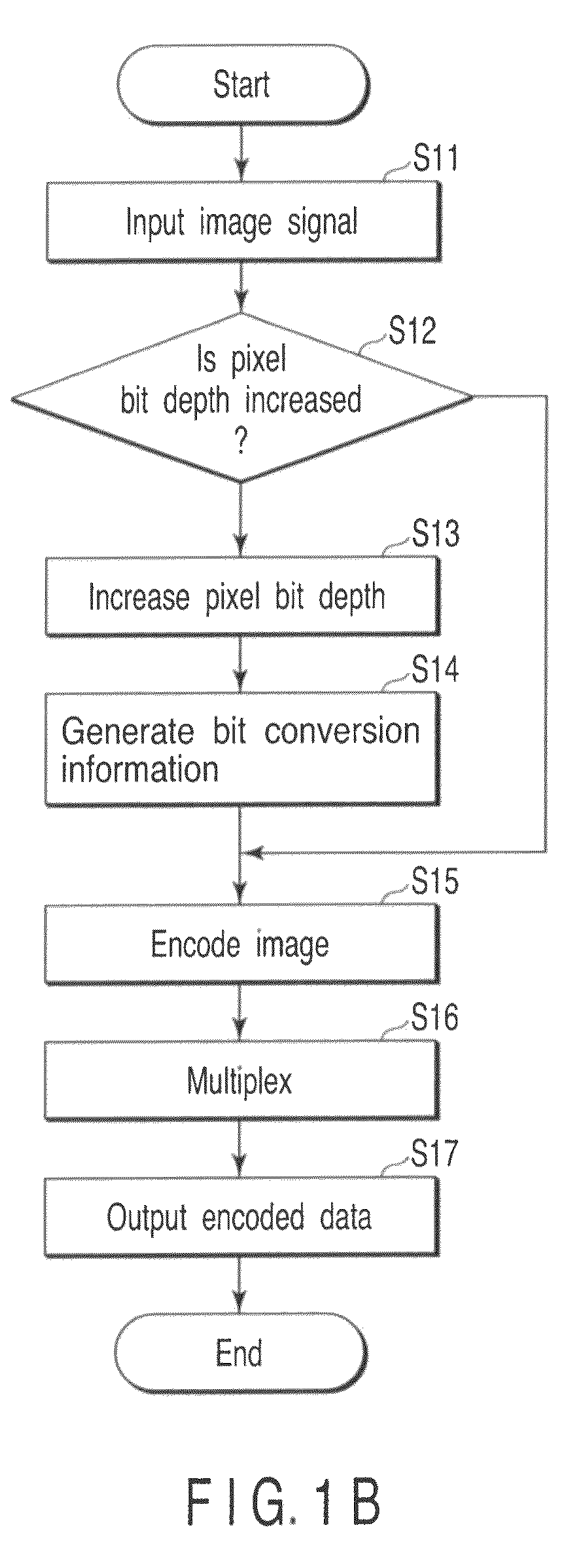
[0078]There will now be described an operation of the image encoding apparatus with reference to the flow chart of FIG. 1B. A video signal is input to this image encoding apparatus as an input image signal 100, for example, in units of one frame (S11). The pixel bit depth increase unit 1001 ...

second embodiment

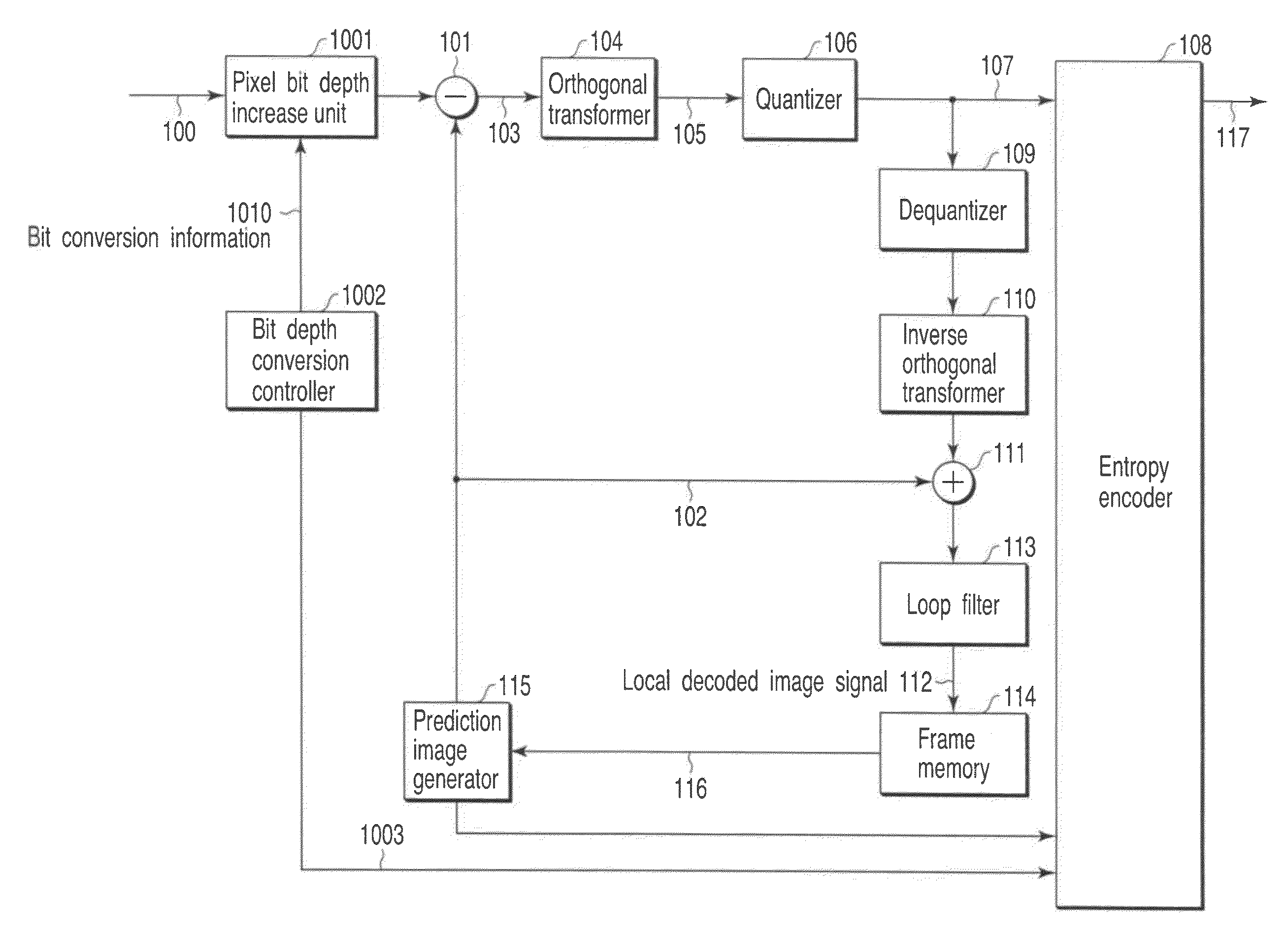
[0119]There will be described configuration of an image encoding apparatus for video encoding related to the second embodiment referring to FIG. 9A. As shown in FIG. 9, this image encoding apparatus comprises a pixel bit depth increase unit (pixel bit depth converter) 1001, a bit depth conversion controller (bit depth conversion controller) 1002, a subtracter 101, an orthogonal transformer 104, a quantizer 106, a dequantizer 109, an inverse orthogonal transformer 110, an adder 111, a loop filter 113, a frame memory 114, a prediction image generator 115, and an entropy encoder 108. The output of the pixel bit depth increase unit 1001 receiving an input image signal is connected to the entropy encoder 108 through the subtracter 101, orthogonal transformer 104 and the quantizer 106. The output of quantizer 106 connected to the prediction image generator 115 through the dequantizer 109, the inverse orthogonal transformer 110, the adder 111, the loop filter 113, and the frame memory 114....

third embodiment

[0132]Configuration of the image encoding apparatus for video encoding according to the third embodiment of the present invention is shown in FIG. 11A. This image encoding apparatus is a configuration approximately similar to the configuration example shown in the second embodiment (FIG. 9), but differs from the second embodiment in the points of providing the pixel bit depth converter 1005 on the previous stage of the frame memory 114 and the pixel bit depth converter (pixel bit depth converter) 1006 on the rear stage of the frame memory 114.

[0133]There will now be described an operation of this image encoding apparatus with reference to FIG. 11B. A video signal is input to this image encoding apparatus as the image signal 100 in units of a frame, for example (S51). The pixel bit depth increase unit (pixel bit depth converter) 1001 does processing for increasing a value of each pixel of the input image signal 100 of N bit depth to (N+M) bit depth larger than N bits by M bits (S52)....


PUM


Abstract

An image encoding apparatus includes a pixel bit depth increase converter to convert bit depth of each pixel of an input image to output a converted input image and output bit conversion information indicating the number of bits changed by conversion, an image encoder to encode the input converted input image to output encoded image information, and a multiplexer to multiplexes the bit conversion information and encoded image information.

Description

CROSS REFERENCE TO RELATED APPLICATIONS[0001]This is a Continuation Application of PCT Application No. PCT / JP2007 / 057197, filed Mar. 30, 2007, which was published under PCT. Article 21(2) in Japanese.[0002]This application is based upon and claims the benefit of priority from prior Japanese Patent Application No. 2006-095597, filed Mar. 30, 2006, and International Application No. PCT / JP2006 / 320876, filed Oct. 19, 2006, the entire contents of both of which are incorporated herein by reference.BACKGROUND OF THE INVENTION[0003]1. Field of the Invention[0004]The present invention relates to an image encoding apparatus for use in a moving image or a still image and a method and an image decoding apparatus and a method.[0005]2. Description of the Related Art[0006]H.264 which is a representative video encoding standard system is a lossy compression system which performs orthogonal transform such as discrete cosine transform (DCT) on a prediction error signal between an input signal and a p...

Claims


Application Information

Patent Timeline
Patent Type & Authority Patents(United States)
IPC IPC(8): G06K9/36G06K9/46H04N19/50H04N19/102H04N19/136H04N19/196H04N19/423H04N19/46H04N19/467H04N19/503H04N19/51H04N19/523H04N19/593H04N19/60H04N19/61H04N19/70H04N19/82H04N19/85H04N19/91
CPCH04N21/23892H04N21/8358H04N19/176H04N19/70H04N19/46H04N19/51H04N19/61H04N19/117H04N19/126H04N19/14H04N19/174H04N19/184H04N19/467H04N19/82H04N19/40H04N21/236H04N19/146
Inventor NODA, REIKOCHUJOH, TAKESHI
Owner KK TOSHIBA
Why Eureka
Try Eureka