
Motorized three-wheeled vehicle rear steering mechanism

a three-wheeled vehicle and rear steering technology, which is applied in the direction of power steering, fluid steering, vehicle components, etc., can solve the problems of less stable condition, increased potential problems, and vehicle can roll, so as to improve handling, performance and safety, and facilitate the operator to turn. , the effect of reducing the turning radius

Inactive Publication Date: 2013-12-17
DANIELS BEN
View PDF24 Cites 6 Cited by
  • Summary
  • Abstract
  • Description
  • Claims
  • Application Information

AI Technical Summary

Benefits of technology

The present invention provides a system for steering the rear wheels of a three-wheeled vehicle in coordination with the operator's front wheel movement to improve handling, performance, and safety. The rear wheels are moved left and right by a rear end mounted steering rack that is powered by electric, pneumatic, hydraulic, or other means. The rear steering control computer receives input from sensors to calculate the direction, rate, and degree for the steering rack to turn the rear wheels. Rear steering offers advantages such as being easier to turn, having a smaller turning radius, better straight line stability, better high-speed handling, improved corning performance, improved steering response, and improved safety.

Problems solved by technology

If the forces become too great the vehicle can roll over.
This is a greater potential problem in a three-wheeled vehicle that has two rear wheels and only one front wheel situated in line with the vehicle's centerline.
This body roll shifts the center of gravity to the outside wheel in curves and creates a less stable condition.
The sharper the turn and the higher the speed the greater the resulting body roll and the less stable the three-wheeled vehicle becomes.
A more rigid non-independent rear suspension design wherein the left and right rear wheels are linked together and can't move independently reduces this effect, however this design results in greater unsprung weight.
Whereas movement of suspension components, i.e. their ability to track and maintain traction over bumpy or imperfect road surfaces, is inversely proportional to the unsprung weight rigid non-independent designs will result in a far less comfortable ride for the operator and passenger and can result in the operator and passenger and / or the entire vehicle being bounced around when going over bumps as the bumps are not being absorbed by the vehicle's suspension.
In some circumstances, including wet and other slippery road conditions, the small front tire contact area does not generate sufficient traction to turn the vehicle and the front tire will skid along the road surface and the vehicle will keep going in a straight line.
If a larger diameter front tire which has a larger contact patch with the road surface is installed, front wheel traction will be increased however the vehicle will become more difficult to turn due to increased friction from the increased contact patch and increased gyroscopic forces from the increased front wheel mass and will requires greater force from the operator to turn the front wheel.
As the vehicle's speed increases the vehicle will become increasingly difficult to turn as the force required to turn the front wheel increases.
There is no practical way to attach a powered steering mechanism to the front end of a three-wheeled vehicle that uses a motorcycle style front fork to assist with turning the front wheel and thus make steering easier.
First, the tilting mechanisms are complicated and have many component parts and are therefore complicated and expensive to manufacture, and can be prone to component failure.
Second, any tilting system requires the use of motorcycle tires that necessarily have a rounded profile to enable the motorcycle to lean during turns, however a consequence of this design is that a motorcycle tire has a much smaller contact patch with the road surface than a comparable size automobile tire that is not designed to lean.
A design exists that attempts to reduce body roll and improve handling with a rigid rear suspension design that does not allow the vehicle to lean or squat while turning.
The problem with the rigid design that while it eliminates leaning in turns vehicles with this design do not perform well on rough or bumpy roads and provide a poor quality and uncomfortable ride for the operator and passenger for a couple of reasons.
First, this design does not allow the rear wheels to move independently of each other making it more difficult for them to follow the contour of the road.
Second, the unsprung weight of a suspension system having a solid rear axle is greater than for an independent suspension design and thus further limits the ability of the rear wheels to follow bumps in the road and maintain traction as movement is inversely proportional to the unsprung weight.

Method used


Image

  • Motorized three-wheeled vehicle rear steering mechanism
  • Motorized three-wheeled vehicle rear steering mechanism
  • Motorized three-wheeled vehicle rear steering mechanism

Examples


Embodiment Construction

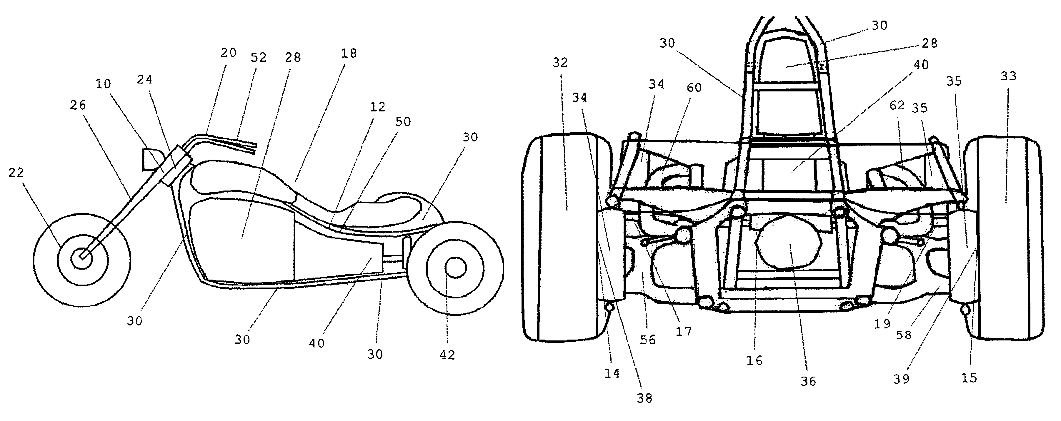
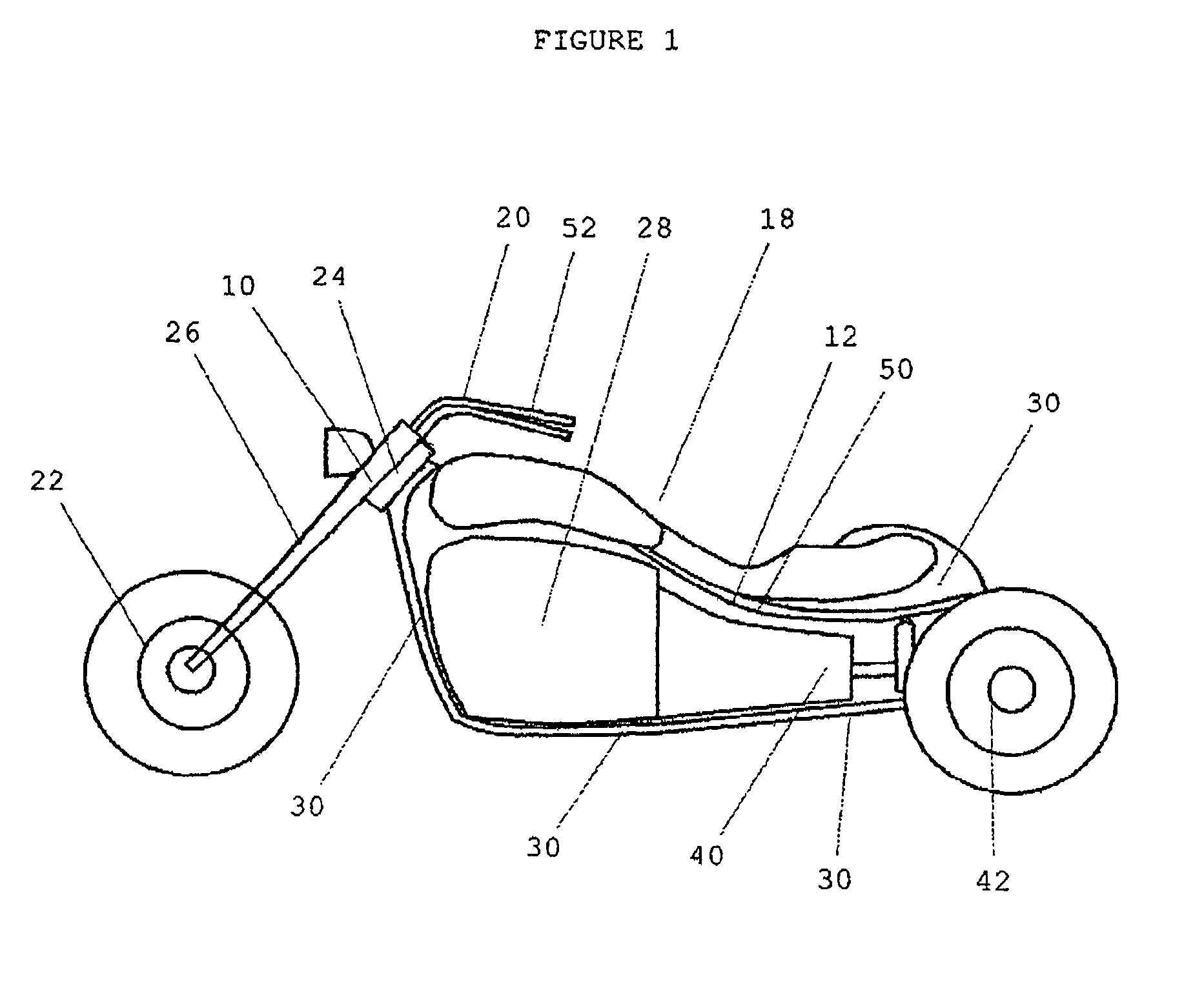
[0026]FIG. 1 is a left view of a complete motorized three-wheeled vehicle 18 with the body removed of the invention. A motorized three-wheeled vehicle 18 has a frame 30 which has steering neck 24 at the front end to which is mounted the front end assembly 26 at the bottom of which is mounted the front wheel assembly 22 and at the top is mounted the handlebars 20 that are used by the operator for the purpose of steering the vehicle.

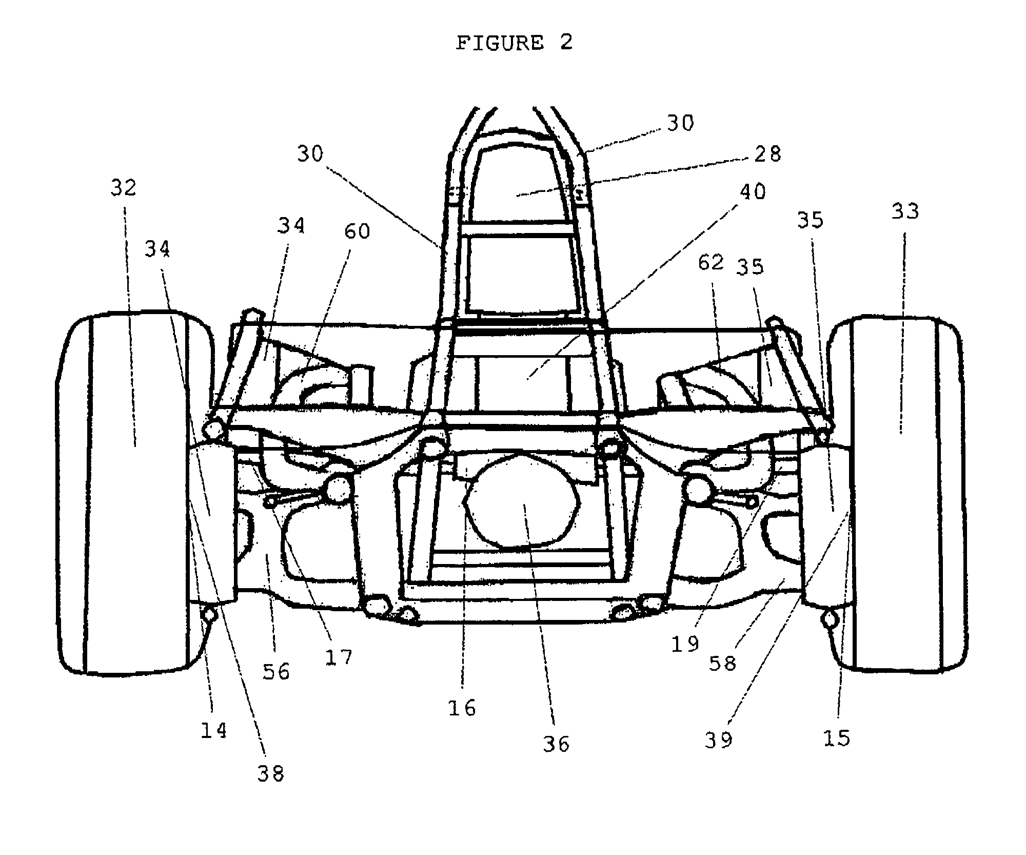
[0027]FIG. 2 is a rear view of a motorized three-wheeled vehicle 18 as shown in FIG. 1. Power for vehicle movement is generated by a motor 28 which can be internal combustion, hybrid, electric or other power source and transmitted to the left rear wheel and tire assembly 32 and the right rear wheel and tire assembly 33 through the transmission 40 and rear end 36. Rear shock absorption is provided by the left rear shock absorbing unit 34 and the right rear shock absorbing unit 35 each of which can be made up of one or more individual shock absorbers.

[0028]F...


PUM


Abstract

A system that steers the rear wheels of the three wheeled vehicle in coordination with the operator turning the front wheel that improves handling, performance and safety. The rear wheels are steered by a rear end mounted powered steering rack that is controlled by a steering control computer that receives input from a variety of sensors including a sensor for vehicle speed and a sensor in the steering neck that measures the angular rotation of the handlebars as they are turned by the operator. Based on these inputs, using proprietary programming the steering control computer calculates the rate, timing and direction to turn the rear wheels. Rear steering offers advantages over front wheel only steering including being easier for the operator to turn the vehicle, a smaller turning radius, better straight line stability, better high speed handling, improved corning performance, improved steering response and improved safety.

Description

FIELD OF THE INVENTION[0001]The present invention relates to a rear steering mechanism for a three-wheeled vehicle and, more particularly, to a system that turns the rear wheels in coordination with the operator's turning of the front wheel.BACKGROUND OF THE INVENTION[0002]It is well known that two standards of ground vehicles exist. One type is represented by two-wheel vehicles (example motorcycles) that are turned by the operator first countersteering (turning the handlebars slightly in the opposite direction of the desired turn) then leaning into the turn and keeping the center of gravity in the plane of the apparent vertical due to combined gravitational and centrifugal forces. Lean angle is determined by speed and turn radius, i.e. the faster the speed and the tighter the turn radius the more the operator is required to lean the motorcycle while turning. This lean also serves to stabilize the motorcycle throughout the turn.[0003]The other type is represented by vehicles with st...

Claims


Application Information

Patent Timeline
Patent Type & Authority Patents(United States)
IPC IPC(8): B62D61/06
CPCB62D7/148B62D7/159B62K5/027B62K5/08
Inventor DANIELS, BEN
Owner DANIELS BEN
Learn More