Conductive terminal with a central bulged portion configured for swinging relative to a base material

a technology of conductive terminals and bulges, applied in the direction of coupling device connections, electric discharge lamps, electric discharge tubes, etc., can solve the problems of reducing the transmission rate of portable electronic devices and ensuring the stability of data transmission of portable electronic devices, and achieves good reliability and effective contact

Active Publication Date: 2013-12-17
APTOS TECH +1
View PDF7 Cites 0 Cited by
  • Summary
  • Abstract
  • Description
  • Claims
  • Application Information

AI Technical Summary

Benefits of technology

[0007]Accordingly, the present invention is directed to a portable electronic device able to keep effective contact between the conductive terminals and the contact-pads and have good reliability.
[0019]Based on the description above, the invention can avoid the poor contact problem between the conductive terminals and the second contact-pads through an appropriate structure design of the conductive terminals. Both ends of each the conductive terminal herein are designed similar to both ends of a lever and are suitable to swing relatively to the base material around the bottom of the central portion as a pivot. When the portable electronic device is plugged into a transmission receptacle, an external force applied by the transmission receptacle presses an end of the conductive terminal to make the conductive terminal and the second contact-pad keep close contact. In addition, the contact area between the conductive terminal and the second contact-pad is increased along with the increasing applied force so as to advance the transmission rate of the portable electronic device and further ensure the data transmission stability thereof.

Problems solved by technology

Therefore, when the contact between a terminal and a contact-pad is poor, the transmission rate of the portable electronic device is reduced and further the data transmission stability of the portable electronic device is not ensured.

Method used


Image

  • Conductive terminal with a central bulged portion configured for swinging relative to a base material
  • Conductive terminal with a central bulged portion configured for swinging relative to a base material
  • Conductive terminal with a central bulged portion configured for swinging relative to a base material

Examples


Embodiment Construction

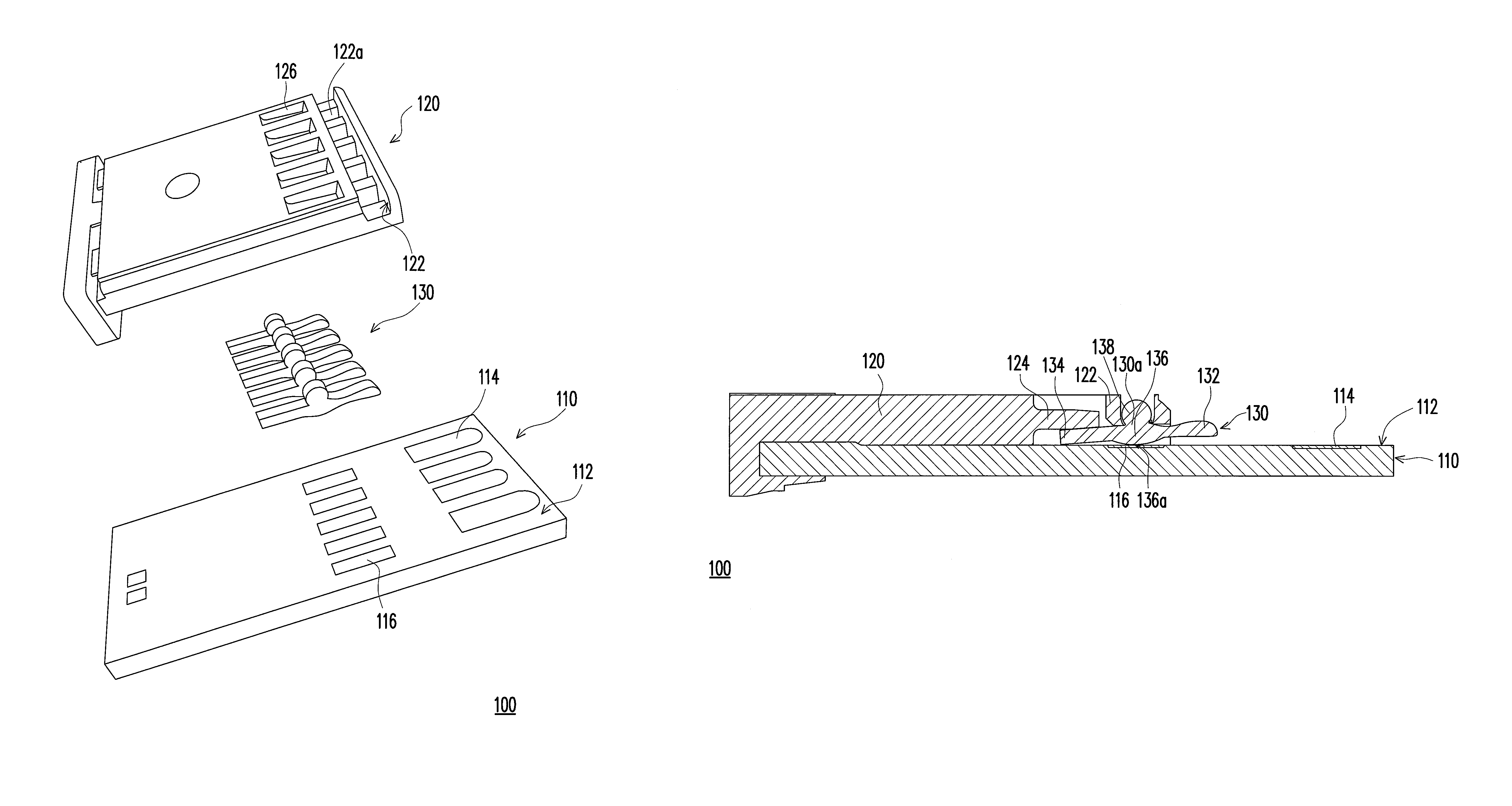
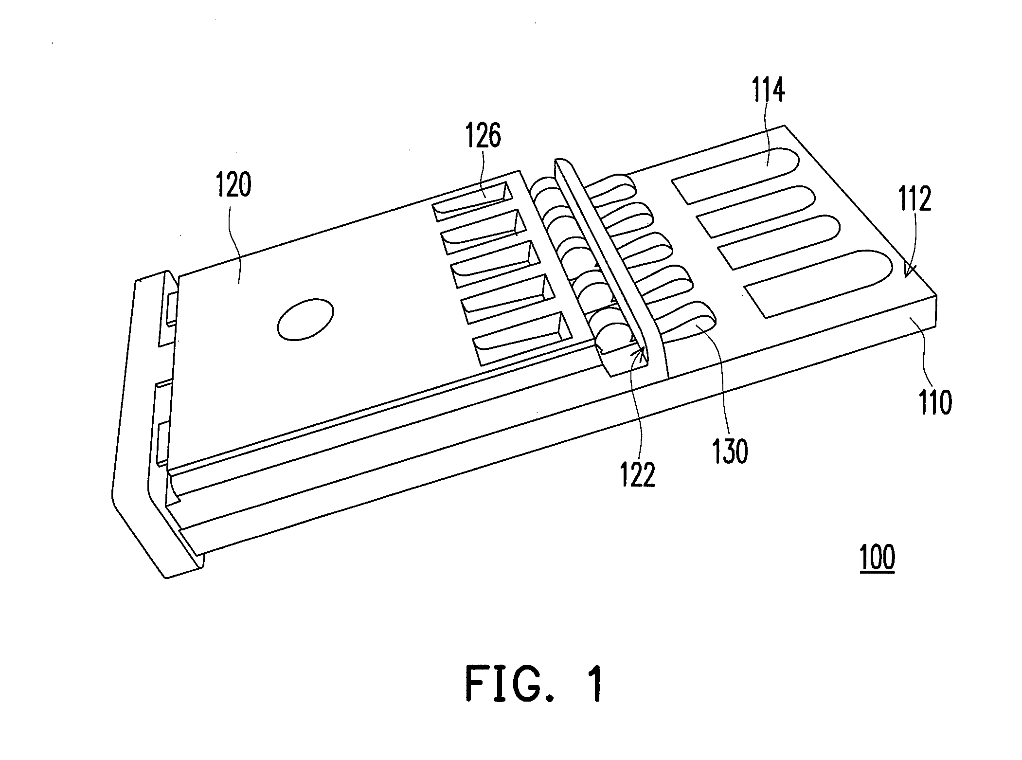
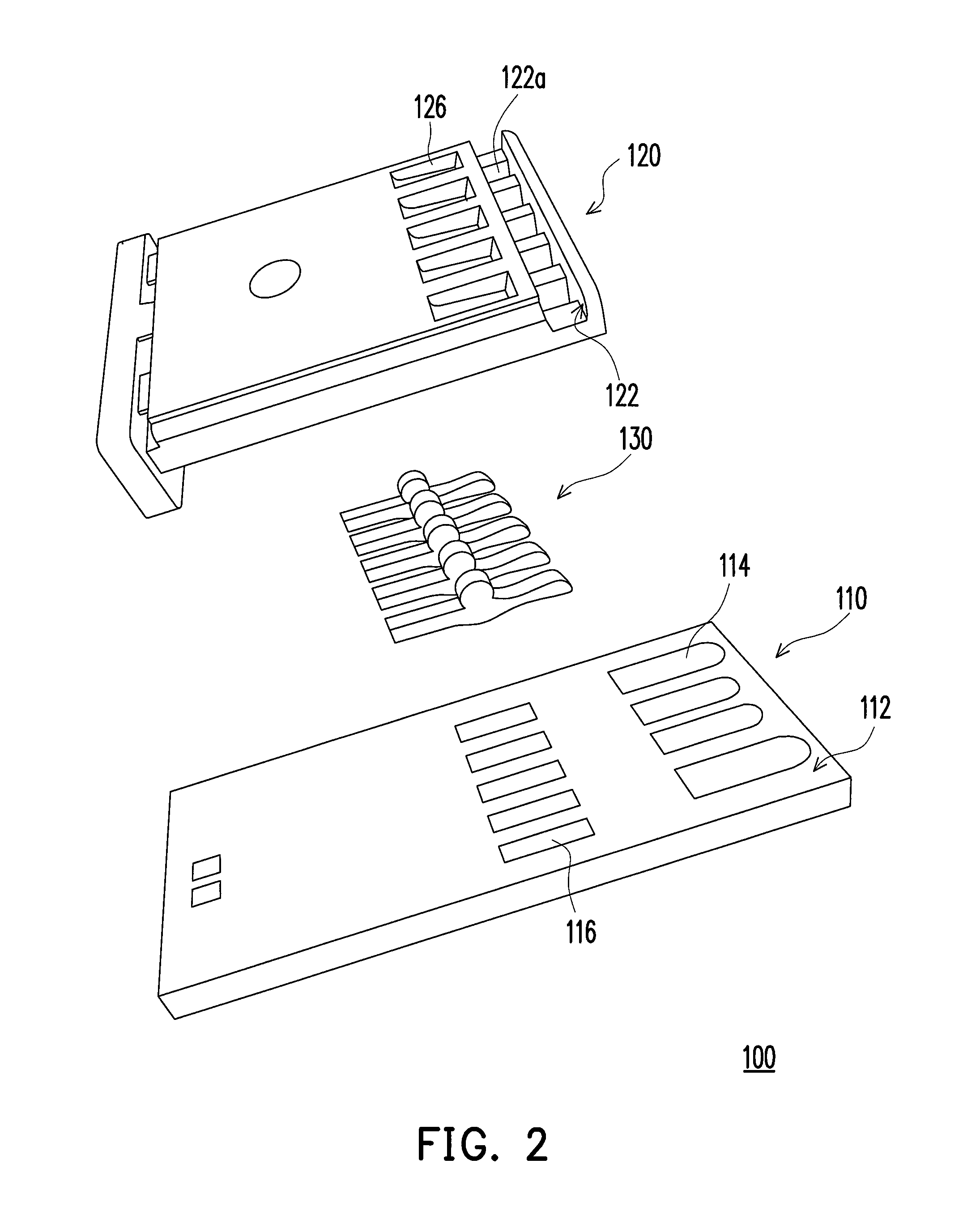
[0033]FIG. 1 is a diagram of a three-dimensional diagram of a portable electronic device according to an embodiment of the present invention and FIG. 2 is an exploded diagram of the portable electronic device of FIG. 1. Referring to FIGS. 1 and 2, a portable electronic device 100 of the embodiment is compatible with the USB 2.0 / 3.0 transmission interface and includes a base material 110, a fixing-cover 120 and a plurality of conductive terminals 130 (five terminals are shown in the figures).

[0034]The base material 110 has a first surface 112 and the base material 110 includes a plurality of first contact-pads 114 and a plurality of second contact-pads 116 both located on the first surface 112. The base material 110 of the embodiment includes a substrate, a chip and a circuit therein, in which the first contact-pads 114 and the second contact-pads 116 can be directly fabricated by using the currently existed production flow procedure of USB2.0 on the substrate. The chip is electrical...


PUM


Abstract

A portable electronic device includes a base material, a fixing-cover and conductive terminals. The base material has first contact-pads and second contact-pads. The fixing-cover is disposed on a first surface and exposes the first contact-pads. The fixing-cover has a clamp portion. The terminals are disposed on the second contact-pads, wherein a first end of each the terminal extends out of the fixing-cover. A second end leans against the fixing-cover. A central portion is located between the two ends, wherein the bottom of the central portion bulges and contacts the corresponding second contact-pad, and the two ends can swing relatively to the base material around the bottom of the central portion as the pivot. The central portion has a positioning portion formed in direction facing the opening and the positioning portion is embedded in the opening.

Description

CROSS-REFERENCE TO RELATED APPLICATION[0001]This application claims the priority benefits of Taiwan application serial no. 101202005, filed on Feb. 3, 2012, and Taiwan application serial no. 101205620, filed on Mar. 28, 2012. The entirety of each of the above-mentioned patent applications is hereby incorporated by reference herein and made a part of specification.BACKGROUND[0002]1. Field of the Invention[0003]The invention generally relates to a portable electronic device, and more particularly, to a portable electronic device compatible with the architectures of universal serial bus (USB) 3.0 and USB 2.0.[0004]2. Description of Related Art[0005]The USB interface is a common hot-plug interface adopted by electronic apparatuses available on the existing market. To respond the demand of high data transmission volume and high transmission rate, the signal transmission specification of a USB is also evolved from USB 2.0 to USB 3.0. In comparison with the conventional USB 2.0 with 480M b...

Claims


Application Information

Patent Timeline
Patent Type & Authority Patents(United States)
IPC IPC(8): H01R39/00
CPCH01R24/64H01R29/00H01R2107/00
Inventor LIN, KUO-HUAYANG, TSUNG-YENLU, CHIEN-HSIENSUNG, YEH
Owner APTOS TECH
Why Eureka
Try Eureka