Particle acceleration devices and methods thereof

a particle acceleration and accelerator technology, applied in accelerators, electric discharge tubes, klystrons, etc., can solve the problems of less stored energy for the same accelerator gradient, small power loss, and high microwave power level to be sustained

Inactive Publication Date: 2013-12-17
SCHLUMBERGER TECH CORP
View PDF13 Cites 2 Cited by
  • Summary
  • Abstract
  • Description
  • Claims
  • Application Information

AI Technical Summary

Benefits of technology

[0012]At least one embodiment of the particle acceleration scheme is disclosed for use in subterranean formations such as for borehole and well-logging applications. In this scheme, particle beams of electrons or ions can be accelerated by the localized electric fields oscillating at high frequencies in resonant photonic band gap cavities. By employing one or multiple evacuated cavities structures, particle beams confined to a vacuum system can be accelerated up to energies of several MeV. Such energetic particle beam can then directed toward one or more targets of many possible materials, to generate gamma-ray or neutron radiation fields. With this device, it is possible to develop a compact, efficient borehole accelerator tool with which it becomes possible to perform a variety of well-logging measurements while overcoming the operational and security risks associated with the high-activity radio-chemical gamma or neutron sources typically used in the well-logging industry. For the purposes of this invention, borehole logging can be considered the science dedicated to measurements of rock or reservoir geophysical properties in subsurface wells.
[0013]An advantage of many of the schemes disclosed in this invention is improved power efficiency: power consumption is a pressing demand for borehole tools. It is estimated that, near-term, only a few kW of average power will be available in a wire-line configuration. However only a fraction of that power will be available to the accelerator tool and in addition the required high microwave power levels must be sustained up to very high ambient temperatures. PBG electro-magnetic cavities efficiently confine the accelerating electrical field to a small-volume region, resulting in less stored energy for the same accelerator gradient and smaller power losses.
[0014]A further advantage of the scheme according to the invention is that the cavity comprising dielectric rods with a low loss factor gives higher Q-factors compared to a cavity with metallic rods such as that of U.S. Pat. No. 6,801,107 B2 by Chen et al. A high cavity quality factor results in a further reduction of input power requirements. This increase in efficiency is important for borehole applications for the reasons given above.

Problems solved by technology

However only a fraction of that power will be available to the accelerator tool and in addition the required high microwave power levels must be sustained up to very high ambient temperatures.
PBG electro-magnetic cavities efficiently confine the accelerating electrical field to a small-volume region, resulting in less stored energy for the same accelerator gradient and smaller power losses.

Method used


Image

  • Particle acceleration devices and methods thereof
  • Particle acceleration devices and methods thereof
  • Particle acceleration devices and methods thereof

Examples


Embodiment Construction

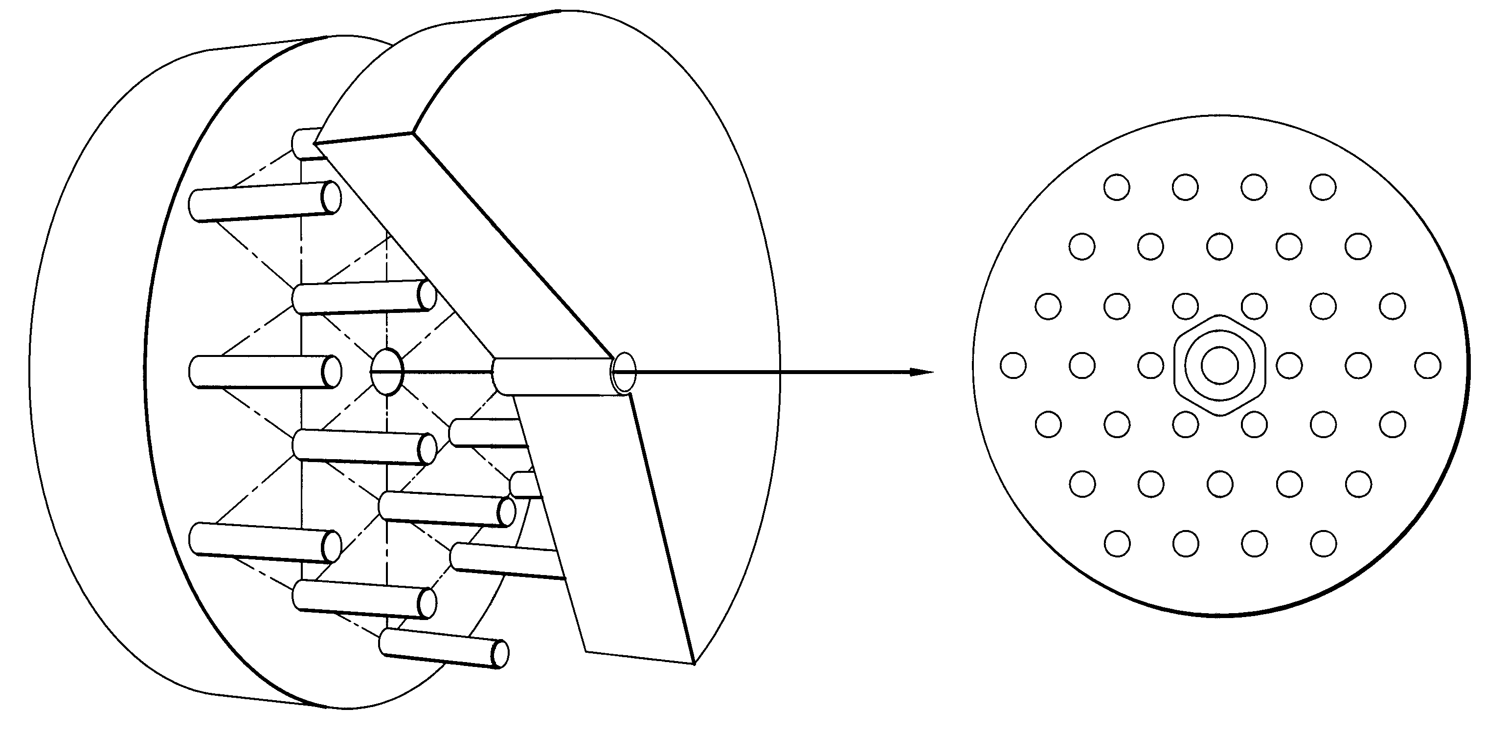
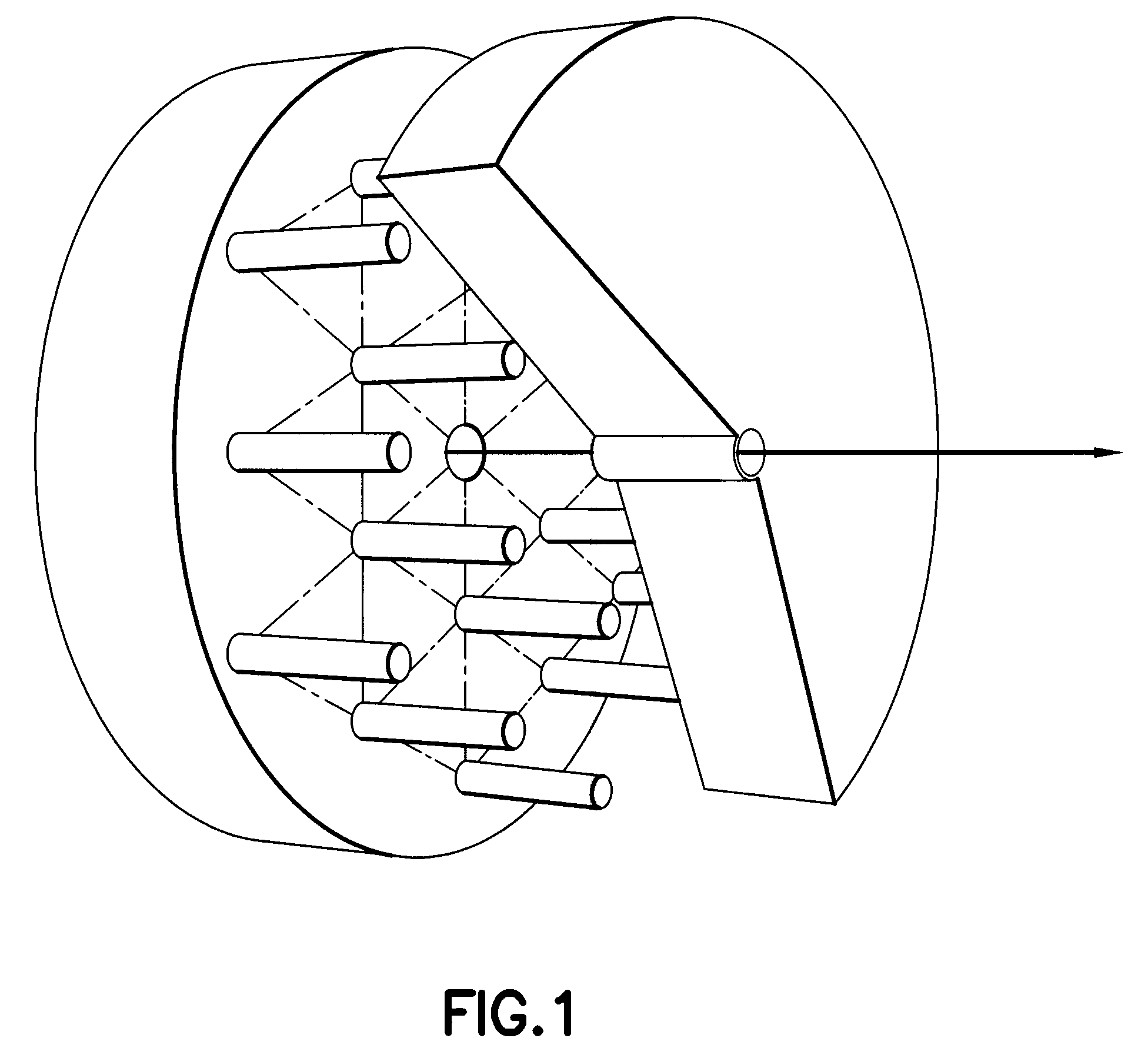
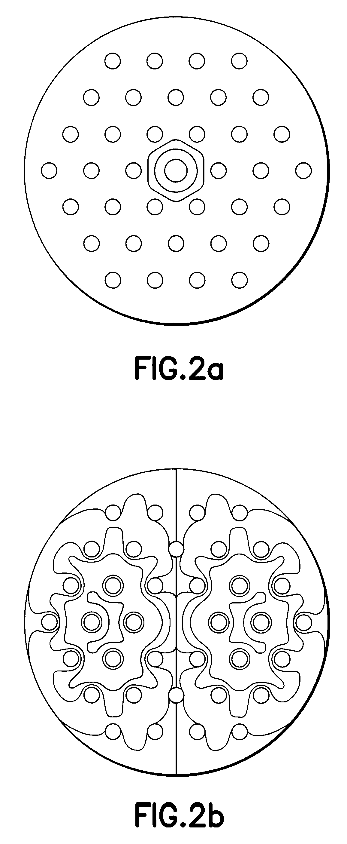
[0029]A particle accelerator scheme is disclosed for example in the implementation to borehole and well-logging applications. In this scheme, particle beams of highly relativistic electrons or ions are created by passage through one or multiple acceleration cells, some or all of which may be realized with a photonic band-gap cavity. Each cavity acts as a means to couple a high electric field to particles travelling in a vacuum enclosure inside a geometrically constrained logging tool. In particular, for a particle accelerator cavity to be used in a subterranean environment, e.g., down-hole tool, a set of optimizations is required that is over and above the stated prior art. For example, the PBG geometry and materials in terms of RF power losses must be optimised, as well as the opening for the beam and coupling to external RF sources. New implementations become possible when utilizing several PBG cavities, similar to the more conventional approaches based on pill-box type of EM reso...


PUM


Abstract

A particle accelerator device structured and arranged for use in a subterranean environment. The particle accelerator device comprising: one or more resonant Photonic Band Gap (PBG) cavity, the one or more resonant PBG cavity is capable of providing localized, resonant electro-magnetic (EM) fields so as to one of accelerate, focus or steer particle beams of one of a plurality of electrons or a plurality of ions. Further, the particle accelerator device may provide for the one or more resonant PBG cavity to include a geometry and one or more material that is optimized in terms of RF power losses, wherein the optimization provides for a PBG cavity quality factor significantly higher than that of an equivalent normally conducting pill-box cavity.

Description

CROSS REFERENCE TO RELATED APPLICATION[0001]This application claims priority to U.S. provisional application Ser. No. 60 / 972,377, filed on Sep. 14, 2007, which is incorporated herein by reference.BACKGROUND OF THE INVENTION[0002]1. Field of the Invention[0003]This invention relates to particle acceleration devices and methods thereof. More particularly, the invention relates to particle acceleration devices and methods used for measuring properties of subterranean formations such as in borehole logging or wellbore applications.[0004]2. Background of the Invention[0005]Nuclear borehole logging measurements typically employ one or more unstable radio-chemical isotopes such as 137Cs or AmBe to generate fixed-energy gamma or neutron radiation (logging sources). Due to the requirements of the oil industry, such sources are of extremely high intensity and radio-activity, often exceeding 2 Ci for 137Cs and 20 Ci for AmBe. As such, their deployment in oilfields worldwide is strictly control...

Claims


Application Information

Patent Timeline
Patent Type & Authority Patents(United States)
IPC IPC(8): H05H9/00
CPCH01P1/2005H05H15/00
Inventor BOTTO, TANCREDIPOITZSCH, MARTIN
Owner SCHLUMBERGER TECH CORP
Why Eureka
Try Eureka