
System for measuring the true dimensions and orientation of objects in a two dimensional image

a two-dimensional image and object technology, applied in the field of medical radiography, can solve the problems of inability to accurately measure the distance or the size, shape and orientation of objects in x-ray images, and the accuracy of work is limited, so as to achieve accurate measurement of objects, maintain measurement accuracy, and accurately measure objects not.

Active Publication Date: 2013-12-17
ORTHOPEDIC NAVIGATION
View PDF18 Cites 42 Cited by
  • Summary
  • Abstract
  • Description
  • Claims
  • Application Information

AI Technical Summary

Benefits of technology

Enables precise three-dimensional measurements and orientation of objects within radiographic images, reducing the need for trial and error in surgical procedures, improving accuracy and reducing the number of x-ray images required, thereby enhancing surgical precision and safety.

Problems solved by technology

As a result, the surgeon can not accurately measure distances or the size, shape, and orientation of objects in x-ray images and has to rely on intuition and experience to determine these parameters.
The problem is especially serious in the case of surgical procedures that must be carried out using frequent x-ray imagery.
In this case accurate work is limited by the ability of the surgeon to know exact values of the above mentioned parameters.
In the absence of this information, time consuming trial and error is needed to complete the procedure and the lack of accurate measurements has been determined to be one of the causes of failures of orthopedic procedures.
Each of the solutions proposed to date, while it might represent an improvement over prior proposals or may give adequate results for certain procedures, has not provided an overall solution.
A surgeon using any of the previous measurement techniques, whether involving using a regular ruler to measure objects directly (not through x-ray) or measuring objects on the image itself will experience the same limitations.
Measuring objects directly is often problematic since access is limited to the objects measured and measuring on the image itself, besides requiring a calibration, can only provide measurements on the projection of the object and in the projection plane.

Method used


Image

  • System for measuring the true dimensions and orientation of objects in a two dimensional image
  • System for measuring the true dimensions and orientation of objects in a two dimensional image
  • System for measuring the true dimensions and orientation of objects in a two dimensional image

Examples


Embodiment Construction

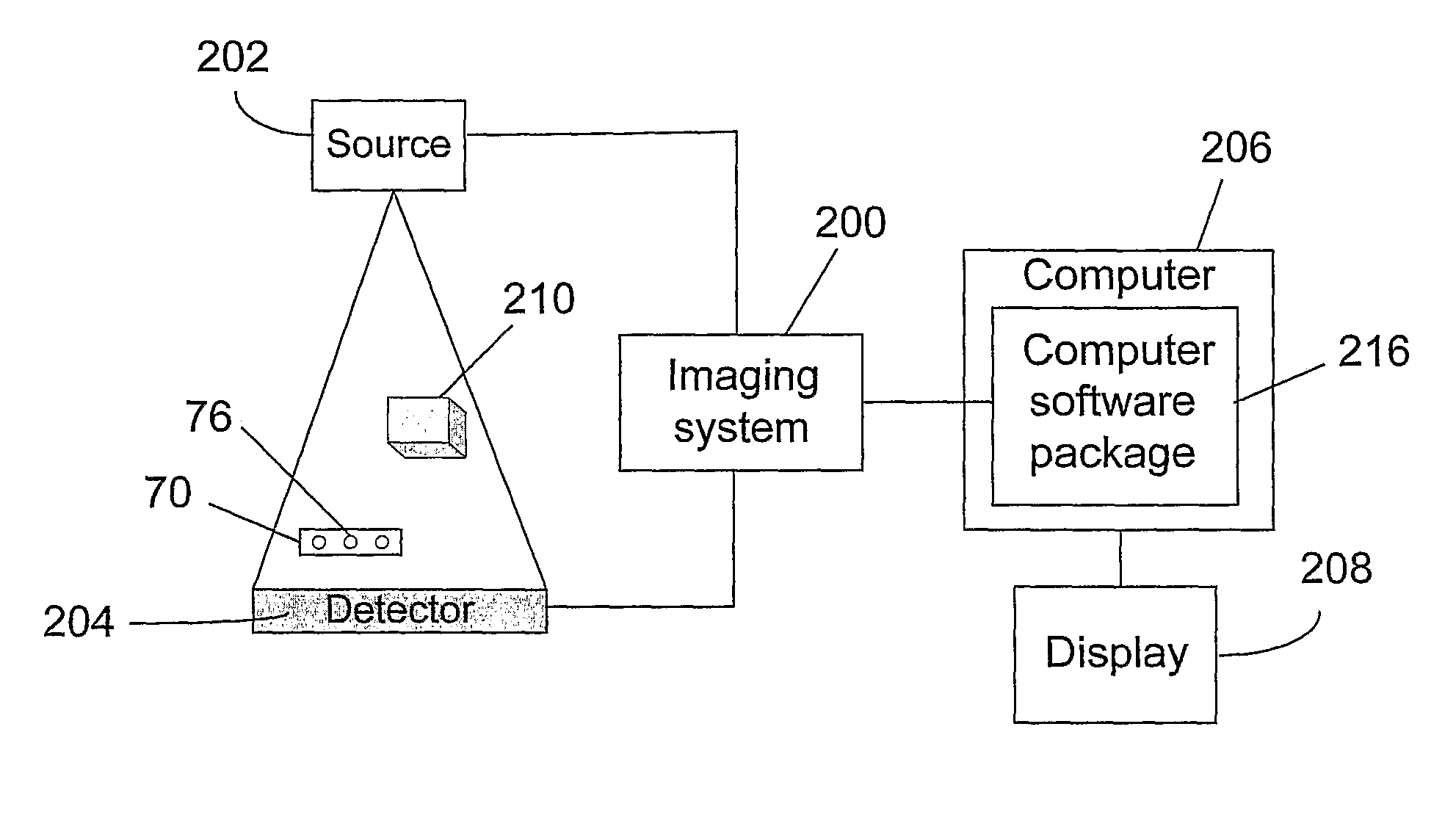
[0049]The invention is a system that can be used for measuring the true dimensions in a specific orientation of objects in two and three dimensional images. In order to illustrate the invention and in preferred embodiments thereof, the images considered herein are radiographic images, in particular x-ray images, wherein by x-ray images are meant radiographic images, fluoroscopic images, digital fluoroscopy images, or images taken using any other type that uses x-rays to obtain them. However it is to be understood that the device and methods of the invention can be used in any imaging situation. In the case of x-ray radiography, the device and system of the invention are used to measure the true dimensions and orientation of objects that appear in the image and to aid the surgeon in the identification and location of surgery tools vs. anatomy in the radiographic image.

[0050]FIG. 16 symbolically shows how the system of the invention is integrated with an imaging system to improve the ...


PUM


Abstract

The invention is a system for measuring the true dimensions and orientation of objects in a two dimensional image. The system is comprised of a ruler comprising at least one set of features each comprised of two or more markers that are identifiable in the image and having a known spatial relationship between them and a software package comprising programs that allow extension of the ruler and other objects in the two dimensional image beyond their physical dimensions or shape. The system can be used together with radiographic imagery means, processing means, and display means to take x-ray images and to measure the true dimensions and orientation of objects and to aid in the identification and location of a surgery tool vs. anatomy in those x-ray images. The invention provides a method of drawing and displaying on a two dimensional x-ray image measurements of objects visible in said image, graphical information, or templates of surgical devices.

Description

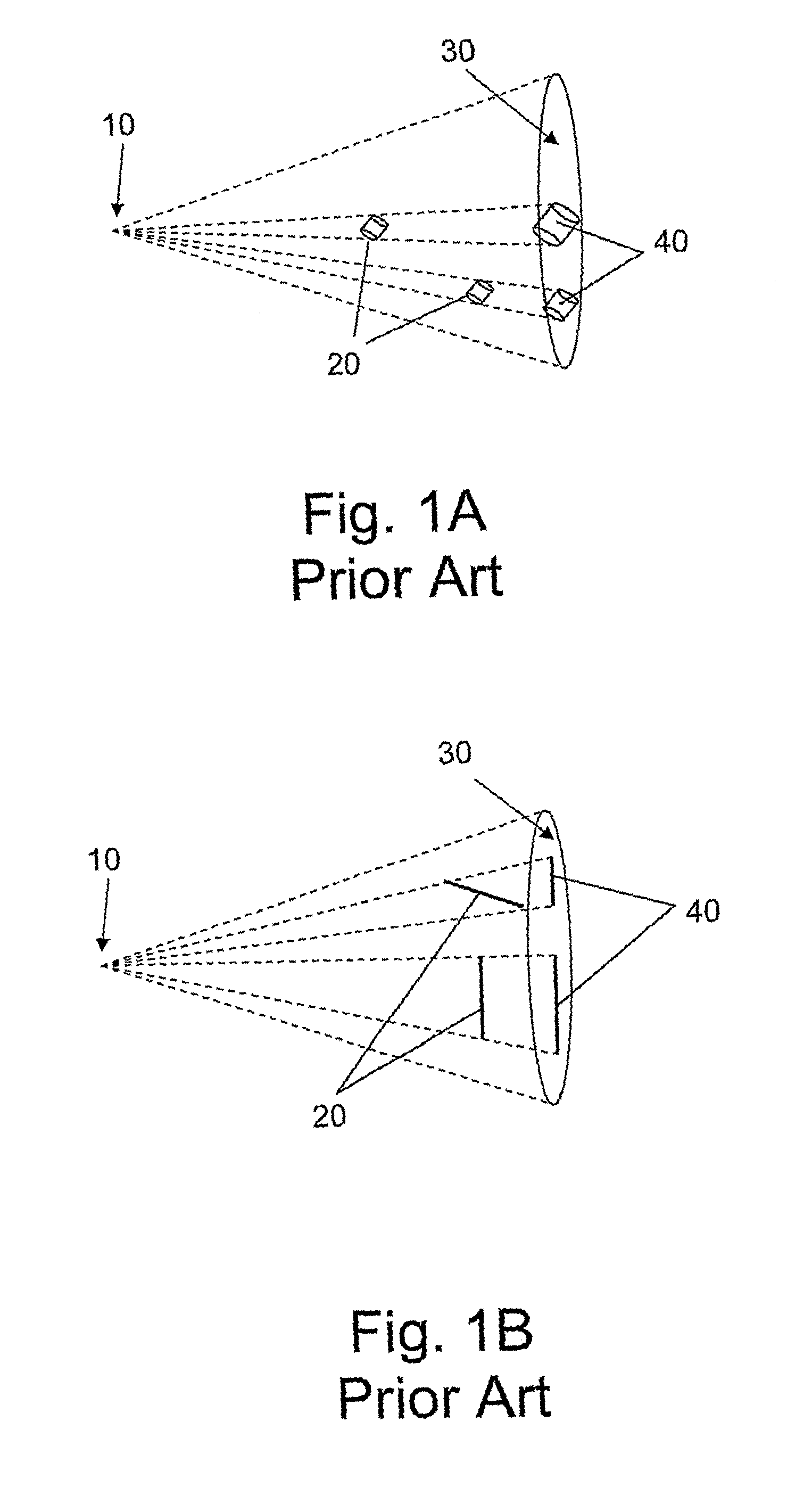
FIELD OF THE INVENTION[0001]The invention is related to the field of medical radiography. More specifically the invention relates to devices and methods of accurately measuring the dimensions in a specific orientation of objects observable in two-dimensional images, e.g. radiographic images.BACKGROUND OF THE INVENTION[0002]The technical problem that is addressed by the present invention has been known since the earliest application of x-rays as an aid in medical diagnostics and the performance of medical procedures. The problem is easily understood with reference to FIG. 1A and FIG. 1B. X-ray source 10 is roughly a point source that emits a cone of x-rays that project an image 40 of radiopaque object 20 on surface 30. Surface 30 is in some cases essentially planar but is usually distorted as a result of the configuration of the equipment used to make the images. The surface 30 can be of any type made sensitive to x-rays, e.g. a sheet of glass or plastic or a thin paper or plastic fi...

Claims


Application Information

Patent Timeline
Patent Type & Authority Patents(United States)
IPC IPC(8): G06K9/32G06K9/00
CPCG06T7/0042A61B6/12A61B19/54G06T11/00G06T19/00G06T2200/04G06T2207/10116G06T2207/30052G06T2207/30204G06T2207/10121G06T2207/30008G06T2207/30021G06T2219/012A61B90/39G06T7/73A61B2090/3966A61B6/461A61B6/5211G06T7/0012
Inventor NATHANIEL, RAMRAPPAPORT, DANDRORI, OREN
Owner ORTHOPEDIC NAVIGATION
Learn More