Electrochromic element and method of forming same

a technology of electrochromic elements and electrochromic elements, applied in the field of electrochromic elements and methods of forming them, can solve the problems of low transmittance of visible light of a specific wavelength, difficult to make the refractive index of a layer adjacent to the electrochromic layer, and high possibility of interference of reflected light with indent light, and achieve the effect of low wavelength dependence of visible light transmittan

Inactive Publication Date: 2013-12-24
CANON KK
View PDF8 Cites 18 Cited by
  • Summary
  • Abstract
  • Description
  • Claims
  • Application Information

AI Technical Summary

Benefits of technology

[0011]Embodiments of the present invention are directed to an electrochromic element including an electrochromic layer made of titanium oxide, having low reflectance on the boundary surface between layers included in the element and having low wavelength dependence of visible light transmittance.
[0013]According to the present invention, the electrochromic layer including a plurality of titanium oxide layers having different refractive indices, so that it is possible to reduce the reflected light generated on the boundary surface between the transparent electrode or electrolyte layer and the electrochromic layer, even if titanium oxide having a high refractive index is used for the electrochromic layer.

Problems solved by technology

Further, the light reflected from the boundary surface interferes with incident light, thereby causing a phenomenon of low transmittance of the visible light of a specific wavelength, i.e., wavelength dependence of visible light transmittance.
However, when an electrochromic element is prepared by an electrochromic material having a high refractive index, it is difficult to make the refractive index of a layer adjacent to the electrochromic layer from such a material that shows a refractive index close to the refractive index of the electrochromic layer.
As a result, the reflectance on the boundary surface is increased, leading to a high possibility of interference of reflected light with indent light.
However, titanium oxide has a high refractive index of approximately 2.5, and therefore it is not easy to reduce the reflectance only by relying on selection of a material of an adjacent layer of the electrochromic layer.

Method used


Image

  • Electrochromic element and method of forming same
  • Electrochromic element and method of forming same
  • Electrochromic element and method of forming same

Examples


Embodiment Construction

[0022]Various exemplary embodiments, features, and aspects of the invention will be described in detail below with reference to the drawings.

[0023]Titanium oxide is attracting attention as an electrochromic material, since its optical characteristic is less dependent on wavelength than those of tungsten oxide and indium oxide.

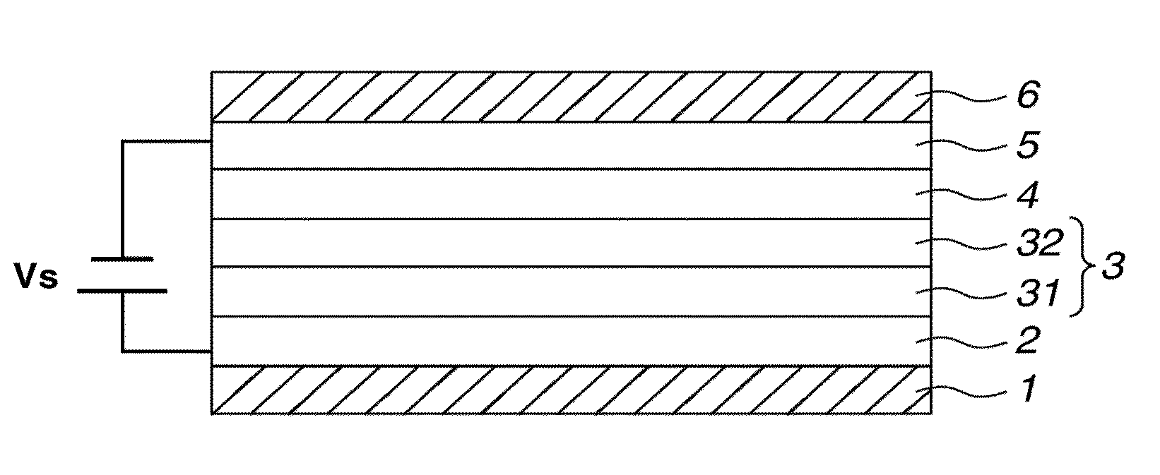
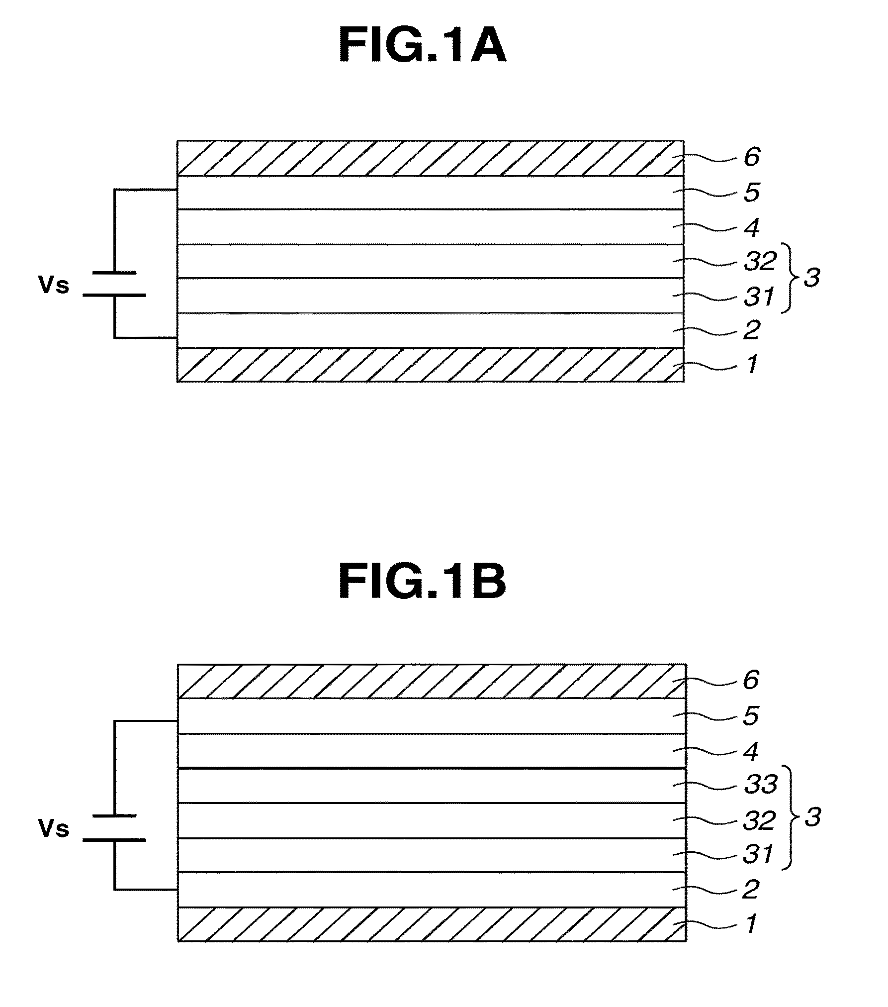
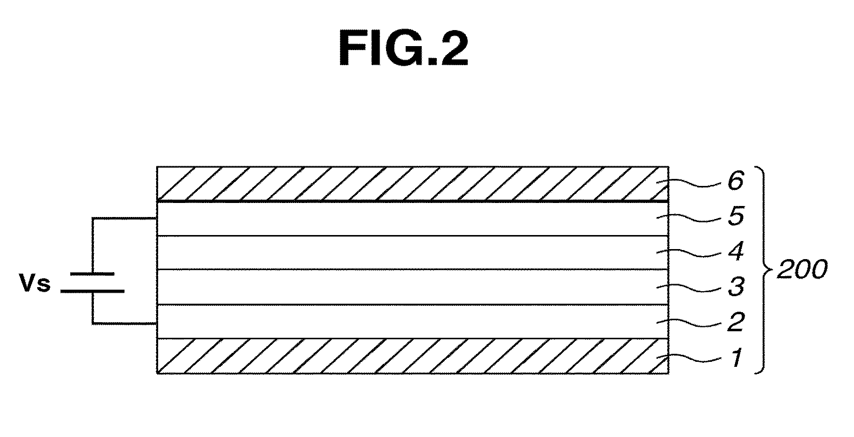
[0024]It is known that the refractive index of a titanium oxide layer can be controlled by controlling the density of the titanium oxide within the layer. However, finding the appropriate structure of the layer has proven to be a difficult task. An electrochromic element according to exemplary embodiments of the present invention includes a plurality of electrochromic layers, and the respective electrochromic layers are made of titanium oxide materials having different densities specifically formed so that refractive indices thereof satisfy predetermined (or desired) mathematica conditions.

[0025]The relationship between the refractive index and the density of a...


PUM

PropertyMeasurementUnit
wavelengthsaaaaaaaaaa
refractive indicesaaaaaaaaaa

Abstract

An electrochromic element includes a pair of transparent electrodes, and an electrolyte layer and an electrochromic layer disposed between the pair of transparent electrodes. Transmittance of light is changed by a voltage applied to the pair of transparent electrodes. The electrochromic layer includes a first electrochromic layer and a second electrochromic layer stacked upon each other. Both of the first and second electrochromic layers are made of titanium oxide. The first electrochromic layer is in contact with one of the pair of transparent electrodes. The second electrochromic layer is in contact with an electrolyte-layer side of the first electrochromic layer. A refractive index n0 of the transparent electrode in contact with the first electrochromic layer, a refractive index n1 of the first electrochromic layer, and a refractive index n2 of the second electrochromic layer satisfy the relationship n0<n1<n2.

Description

BACKGROUND OF THE INVENTION[0001]1. Field of the Invention[0002]The present invention relates to an electrochromic element and methods of forming an electrochromic element capable of controlling transmittance of light.[0003]2. Description of the Related Art[0004]Electrochromism is a phenomenon shown by materials in which a reversible electrochemical reaction is induced in response to a supply of voltage, which changes the absorption wavelength range of the material for visible light, as a result of which the material develops or loses a color. An electrochemically colored or bleached element using such an electrochromic phenomenon is referred to as an “electrochromic element”. An electrochromic element can be used as a light adjustment (or light modulating) element for controlling transmittance of visible light. As used herein, the term “transmittance” is to be accorded its ordinary meaning, which can be loosely defined as the ratio of the light energy falling on a body to that tran...

Claims


Application Information

Patent Timeline
Patent Type & Authority Patents(United States)
IPC IPC(8): G02F1/153G02F1/15
CPCG02F1/153Y10T29/49002
Inventor UEDA, MIKIOKADA, SHINJIROSHIBATA, MASAAKI
Owner CANON KK
Why Eureka
Try Eureka