Cooler assembly for a vehicle cooling system

a vehicle cooling and cooling system technology, applied in the direction of machines/engines, transportation and packaging, light and heating equipment, etc., can solve the problems of high cost of cleaning and maintenance of the vehicle cooling system, and achieve the effect of reducing space availability and simplifying cleaning or maintenance of the cooling uni

Active Publication Date: 2013-12-31
DEERE & CO
View PDF38 Cites 9 Cited by
  • Summary
  • Abstract
  • Description
  • Claims
  • Application Information

AI Technical Summary

Benefits of technology

[0006]Accordingly, an object of this invention is to provide cooling system arrangement which makes possible a simplified cleaning or maintenance of a cooling unit in a vehicle cooling system, even when there is reduced space availability.
[0011]In particular, the sliding rod and the attaching leg may be one piece components of the vehicle cooling system, so that the guide element can be assembled in a single manufacturing cycle by chamfering and bending of a one piece penetrating component. The one piece penetrating component, in this case may be a steel or aluminum alloy full or hollow section. The guide element configured in this way is protected against corrosion by enameling, galvanizing or having its surface treated in similar ways.
[0014]The cleaning or maintenance of the cooling unit can be simplified further if a locking element is provided for the temporary securing of the retaining elements in the operating position or the maintenance position. In particular, the locking element may include a spring element for the establishment of a temporary rest position with the attachment leg of the sliding rod, so that an unintentional sliding of the cooling unit during the cleaning and maintenance operation and / or during the operation of the motor vehicle can be avoided. In addition, or alternately, the cooling unit can be secured in the operating position by establishing a releasable screw connection between the cooling unit or the frame component associated with the vehicle cooling system.
[0017]If the cooling unit is a component of a cooler stack, it is advantageous if of the interior cooling units of the cooler stack can be brought into an extended position, so that its rear side or the front side of the of a cooling unit located immediately behind it are accessible from the outside.
[0018]Furthermore, sensing devices may be provided for sensing the actual position of the retaining element and / or the cooling unit. If the sensing devices sense that the retaining element or the cooling unit are located outside their operating position, the operation of the motor vehicle is prevented, for example, by interrupting the ignition circuit. The sensing device may be a switch element, actuated in the operating position of the retaining element and / or the cooling unit, for example, an electro-mechanical switch or a proximity switch.

Problems solved by technology

Moreover, this cooler assembly can used in a vehicles wherever cleaning and maintenance of the vehicle cooling system would be costly because of construction limitations.

Method used


Image

  • Cooler assembly for a vehicle cooling system
  • Cooler assembly for a vehicle cooling system
  • Cooler assembly for a vehicle cooling system

Examples


Embodiment Construction

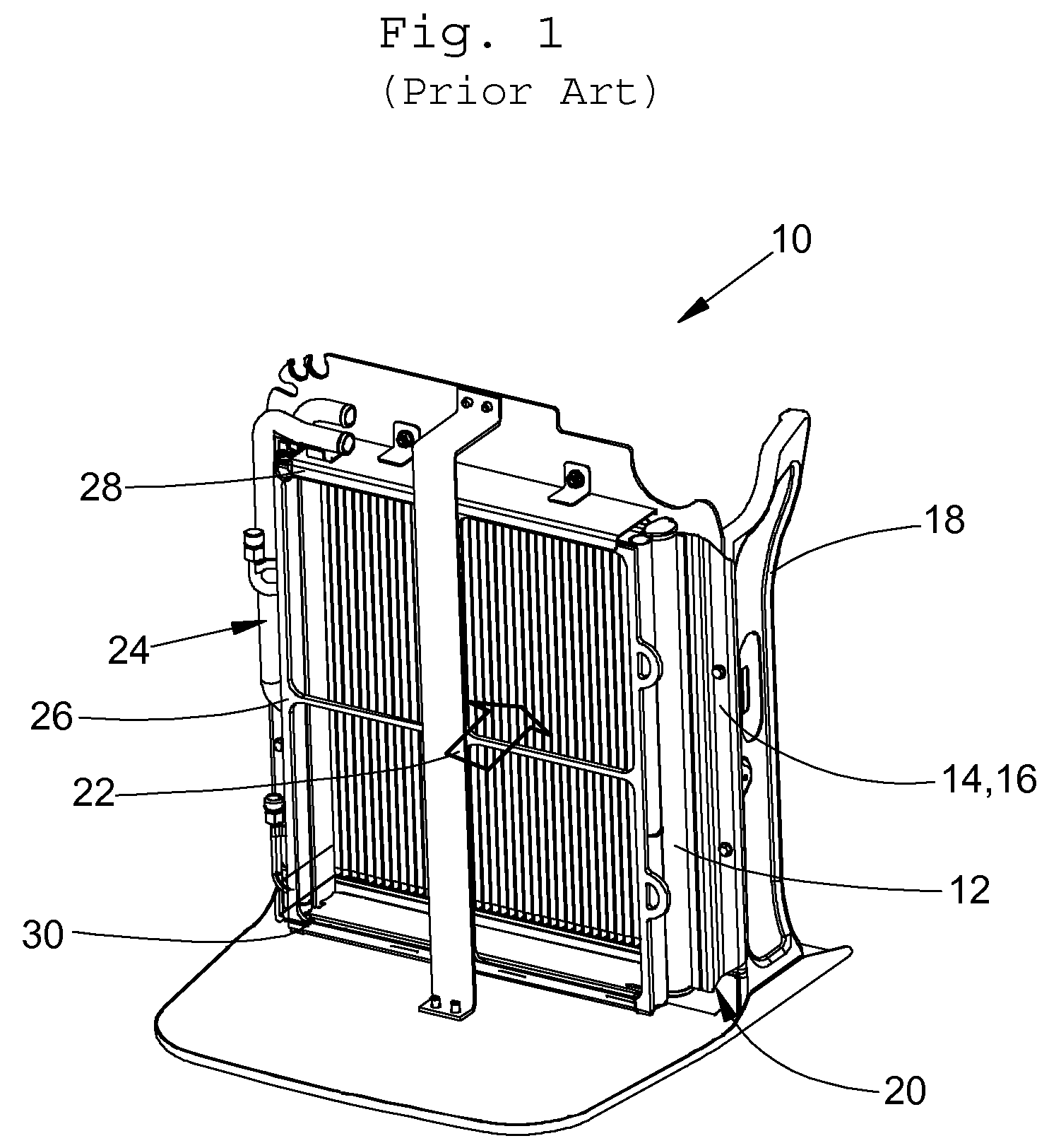
[0027]Referring to FIG. 1, FIG. 1 shows a perspective view of a cooler assembly, known from the state of the art, as it is applied as a vehicle cooling system, not shown, in the engine compartment of an agricultural motor vehicle, for example, a tractor, a harvesting machine or a self propelled sprayer.

[0028]Such a vehicle cooling system, among other items, is known in connection with John Deere Tractors, Model Series 5420, where this is accommodated between an internal combustion engine of the motor vehicle and a vehicle battery in the forward region of the engine compartment for reasons of better accessibility.

[0029]The cooler assembly 10, known from the state of the art, shows several cooling units 12, 14 and 16, arranged one behind the other, in the form of a cooler stack 20, rigidly connected to the frame structure 18 of the cooler assembly 10, where the cooler stack 20 is penetrated by a common cooling air flow 22 for the removal of the exhaust heat resulting from the operatio...


PUM


Abstract

The invention concerns a cooler assembly for a vehicle cooling system, with a cooling unit pivotally attached to a retaining element. The retaining element is slidable in a lengthwise direction along a guide element which is attached to the cooling system, so that the cooling unit can be moved from an operating position by sliding and subsequent pivoting into a maintenance and cleaning position.

Description

FIELD OF THE INVENTION[0001]The present invention relates to a radiator or cooler assembly for a vehicle cooling system, with a retaining element and at least one cooling unit fastened to the retaining element.BACKGROUND OF THE INVENTION[0002]Agricultural vehicles are normally provided with multiple various cooling units for removing the heat rejected during the operation. Usually the cooling units are arranged in the form of a cooler stack located in an engine compartment arranged one behind the other in the common cooling air flow. Contaminants drawn in from the surroundings of the vehicle by the cooling air flow could be deposited on the surface of the cooling unit and thereby impair their cooling ability. Since, above all, the interior cooling units of the cooler stack are not immediately accessible from the outside and therefore cannot be cleaned without difficult disassembly of the vehicle cooling system, the cleaning or maintenance cost is correspondingly high.[0003]Various p...

Claims


Application Information

Patent Timeline
Patent Type & Authority Patents(United States)
IPC IPC(8): B60H1/00
CPCF01P2011/063F01P3/18F01P2070/52B60K11/04B60Y2304/074
Inventor FELL, THOMASKEIM, ANDREASLE, DUONG M
Owner DEERE & CO
Why Eureka
Try Eureka