Hydraulic power generating apparatus

a technology of hydraulic power generation and generating equipment, which is applied in the direction of electric generator control, renewable energy generation, greenhouse gas reduction, etc., can solve the problems of periodic maintenance, maintenance requires great care, and maintenance is inevitable, so as to achieve stable hydraulic power generation and avoid lowering the power generation efficiency. , the effect of easy maintenan

Inactive Publication Date: 2013-12-31
SEABELL INT CO LTD
View PDF16 Cites 17 Cited by
  • Summary
  • Abstract
  • Description
  • Claims
  • Application Information

AI Technical Summary

Benefits of technology

[0015]The hydraulic power generating apparatus of the present invention particularly includes the water collecting plate which collects water into the water inflow opening while intercepting and accumulating water flowing through the waterway, and the movable gate which is capable of changing flow cross-sectional area of water flow acting to the rotor blade top end of the vertical axis turbine as inflowing from the water inflow opening. Therefore, the water level at the upstream side and the opening area of the orifice hole can be adjusted by changing the flow cross-sectional area owing to opening and closing of the movable gate. Accordingly, it is possible to have a flow rate adjusting function without lowering a power generation efficiency. Thus, there arises an effect that stable hydraulic power generation can be continuously performed without depending on water level fluctuation in the waterway. Further, since rotor blade operation can be stopped as blocking water passing toward the vertical axis turbine by completely closing the movable gate, there also arises an effect that maintenance operation can be easily performed.

Problems solved by technology

One is a problem of maintenance.
Here, periodic maintenance is inevitably required to maintain performance thereof.
Thus, there is a problem that maintenance requires great care.
The other is a problem of water level fluctuation.
Accordingly, there has been a possible problem that stable power generation cannot be performed.

Method used


Image

  • Hydraulic power generating apparatus
  • Hydraulic power generating apparatus
  • Hydraulic power generating apparatus

Examples


Embodiment Construction

[0040]In the following, preferable embodiments of the present invention will be described in detail with reference to the attached drawings.

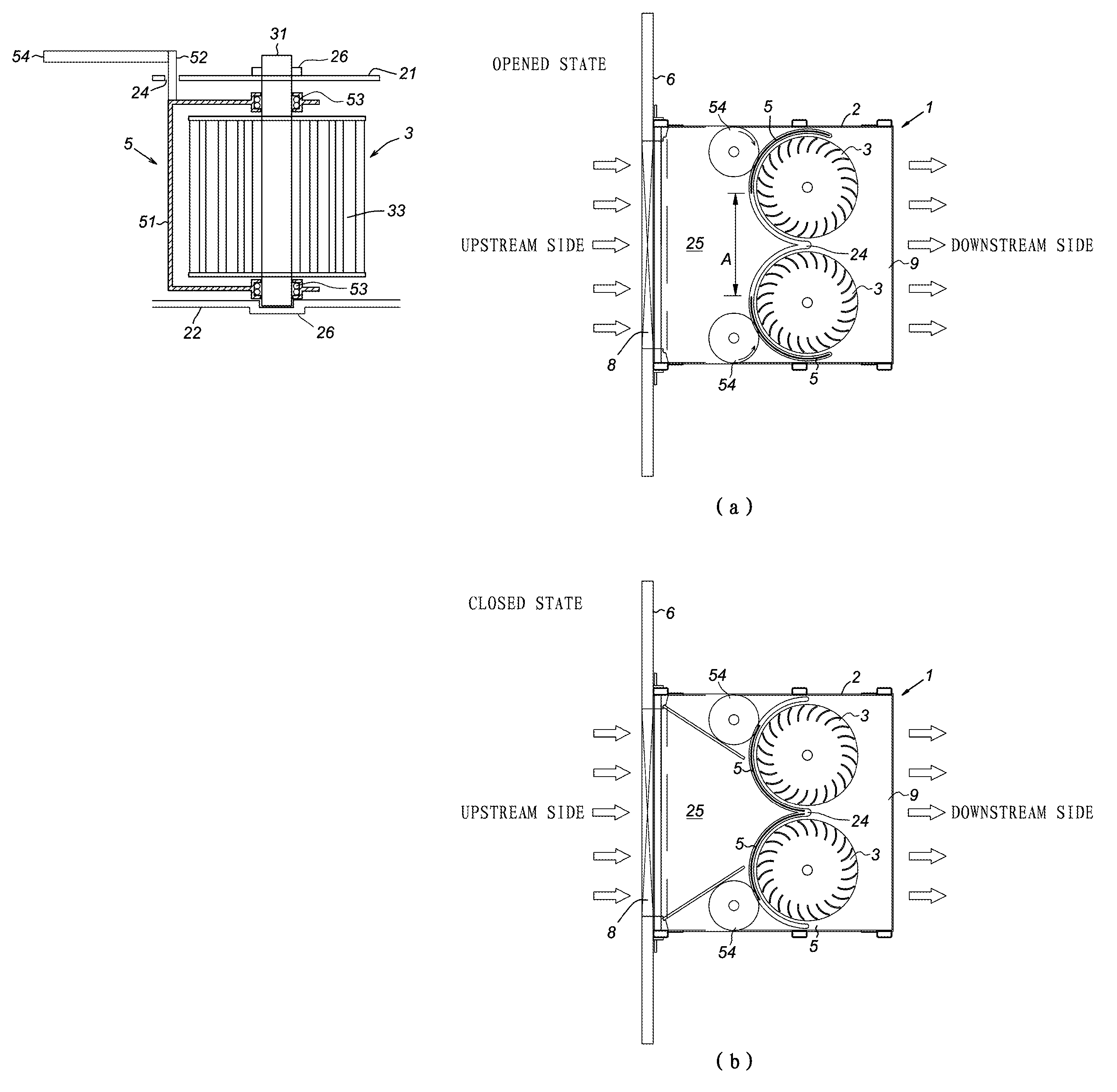
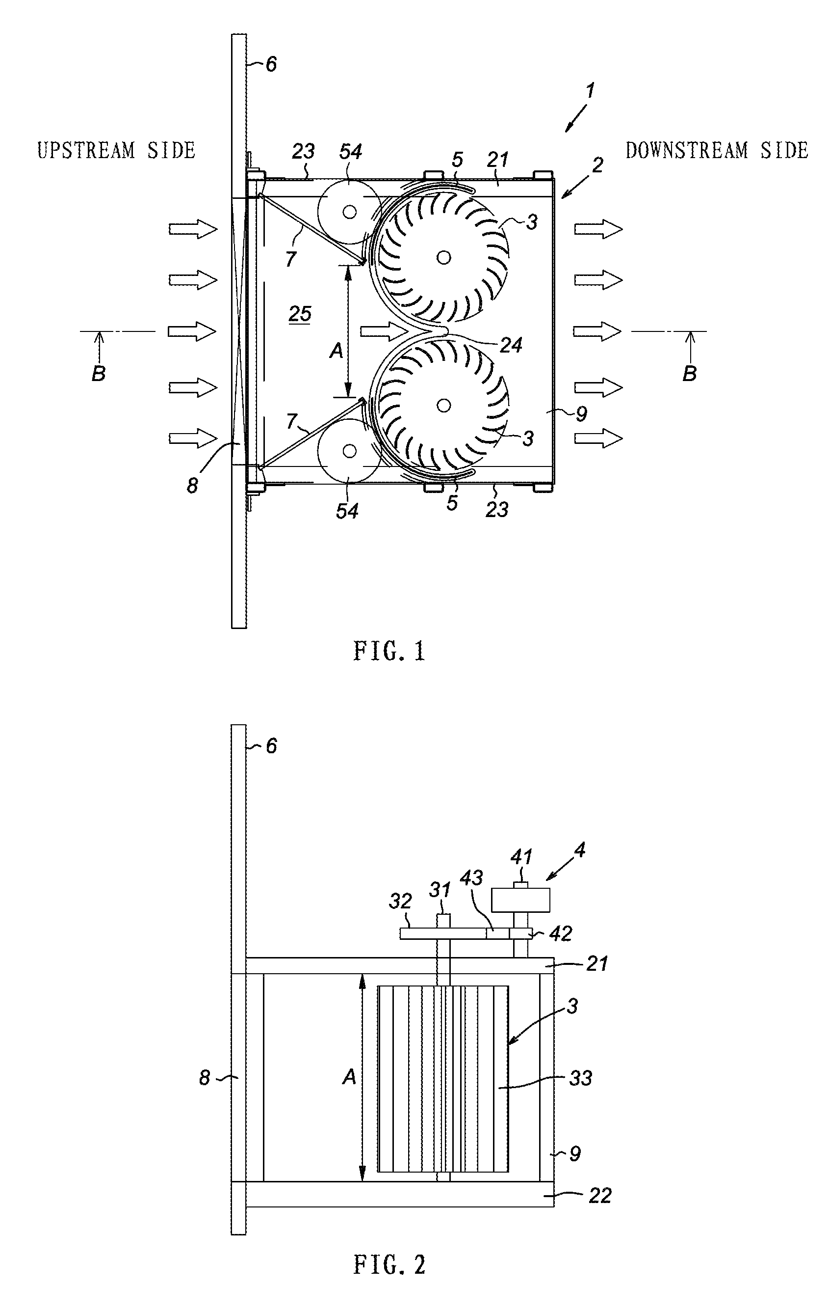
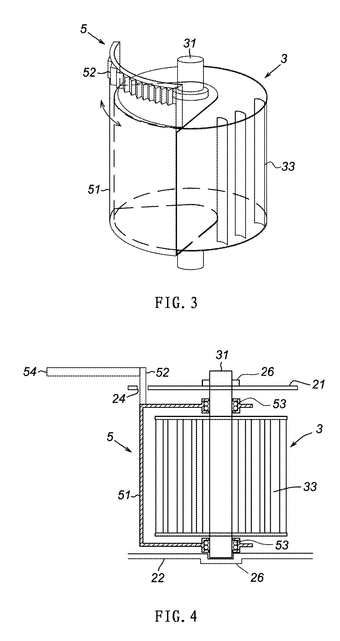
[0041]FIG. 1 is a plane view illustrating an embodiment of a hydraulic power generating apparatus according to the present invention. Here, for facilitating visualization for each structure, FIG. 1 include omission in part on a generator 4, pulleys 32, 42, a belt 43 and a drive shaft 41. FIG. 2 is a cross-sectional view at B-B of FIG. 1. Here, a gear 54, a movable gate 5 and an acceleration plate 7 are omitted for clarifying each structure. FIG. 3 is an explanatory cross-sectional view of a structure of a vertical axis turbine 3 disposed to a hydraulic power generating apparatus 1 as being simplified for clarifying positional relation between the movable gate 5 and the vertical axis turbine 3. FIG. 4 is an explanatory perspective view of a structure of the vertical axis turbine 3 disposed to the hydraulic power generating apparatus 1.

[0042]As il...


PUM


Abstract

The apparatus includes a water collecting plate 6 which collects water into a water inflow opening 8 while intercepting and accumulating water flowing through a waterway, and a movable gate 5 which is capable of changing flow cross-sectional area of water flow acting to the top ends of rotor blades 33 of a vertical axis turbine 3 as inflowing from the water inflow opening 8. Here, owing to changing of flow cross-sectional area with opening and closing of the movable gate 5, a flow rate can be adjusted by changing a water level at the upstream side and opening area of an orifice hole and operation of the rotor blades 33 can be stopped by blocking water passing toward the vertical axis turbine 3.

Description

CROSS-REFERENCE TO RELATED APPLICATION[0001]This application is the U.S. national phase of PCT Appln. No. PCT / PCT / JP2011 / 069889 filed Sep. 1, 2011 which claims priority to Japanese application JP 2011-111809 filed May 18, 2011, the disclosures of which are incorporated in their entirety by reference herein.TECHNICAL FIELD[0002]The present invention relates to a hydraulic power generating apparatus capable of generating power by utilizing water flow.BACKGROUND ART[0003]The inventor has developed a hydraulic power generating apparatus described in Patent literature 1 generating power by utilizing water flow as being installed to a river, an artificial waterway or the like. Such a hydraulic power generating apparatus starts to be installed to a small river and a first-class river.[0004]Owing to power generation performed by utilizing small hydraulic power such as flow in a river, the hydraulic power generating apparatus has been a nonconventional breakthrough apparatus capable of perfo...

Claims


Application Information

Patent Timeline
Patent Type & Authority Patents(United States)
IPC IPC(8): F03B7/00F03B15/14
CPCY02E10/28Y02E10/223F05B2240/40F03B17/063F03B3/183F05B2240/13Y02E10/20
Inventor UNNO, YUJI
Owner SEABELL INT CO LTD
Why Eureka
Try Eureka