Rotary magnus energy harvester

a rotary magnus and energy harvester technology, applied in the direction of electric generator control, renewable energy generation, greenhouse gas reduction, etc., can solve the problems of reducing the overall power generation efficiency of the system, savonius rotors are very inefficient, and cannot rotate faster than the wind speed, so as to increase the torque created by the lift, increase the torque, and increase the effect of torqu

Inactive Publication Date: 2011-01-06
DOUGLAS JOEL S +3
View PDF5 Cites 12 Cited by
  • Summary
  • Abstract
  • Description
  • Claims
  • Application Information

AI Technical Summary

Benefits of technology

[0023]This Magnus cylinder positioning allows the fluid to be accelerated down the longitudinal length of the machine, and be further accelerated by each downstream cylinder, thereby increasing the torque created by the lift of each Magnus cylinder, which in turn translates into increased torque in the second direction, and more energy to drive generators and other useful devices. The present invention is not limited with regard to the number of cylinder pairs, or the type of fan devices used to rotate the cylinders or that can be installed, however, as any number of cylinder pairs can be installed to generate the desired torque.

Problems solved by technology

One drawback of the Magnus type power generators described in the prior art is that in order to harness the power in a moving fluid, the Magnus cylinders must first be rotated using electric motors that are attached to the Magnus cylinder shaft.
This requires the consumption of a large amount of energy to power the electric motors, which in turn decreases the overall power generation efficiency of the system.
Such Savonius rotors are very inefficient, and are not able to rotate faster than the wind speed.
As a result, using prior art designs, it was essentially impossible to increase the rotational speed of the Magnus force providing rotary cylinders beyond the speed of the wind that is powering the system.
As a result, it was difficult to generate large amounts of energy, and such devices were unsuitable for efficient electric power generation.
However as previously discussed, such electrical motor driven systems themselves use electrical power, thus reducing the overall power efficiency of the system, and addition tend to be more expensive and mechanically complex.

Method used


Image

  • Rotary magnus energy harvester
  • Rotary magnus energy harvester
  • Rotary magnus energy harvester

Examples


Embodiment Construction

[0046]As used herein, the term “hydro application” and “hydraulic” are used to describe the use of the energy harvesting device with regard to liquid, and the term “gas application” and “pneumatic” are used to describe the use of the energy harvesting device with regard to gas (e.g., air).

[0047]As used herein, the term “lift” refers to a force that is perpendicular to a direction of fluid flow.

[0048]As used herein, the term “electrical grid” refers to any system used to utilize or transport electrical current.

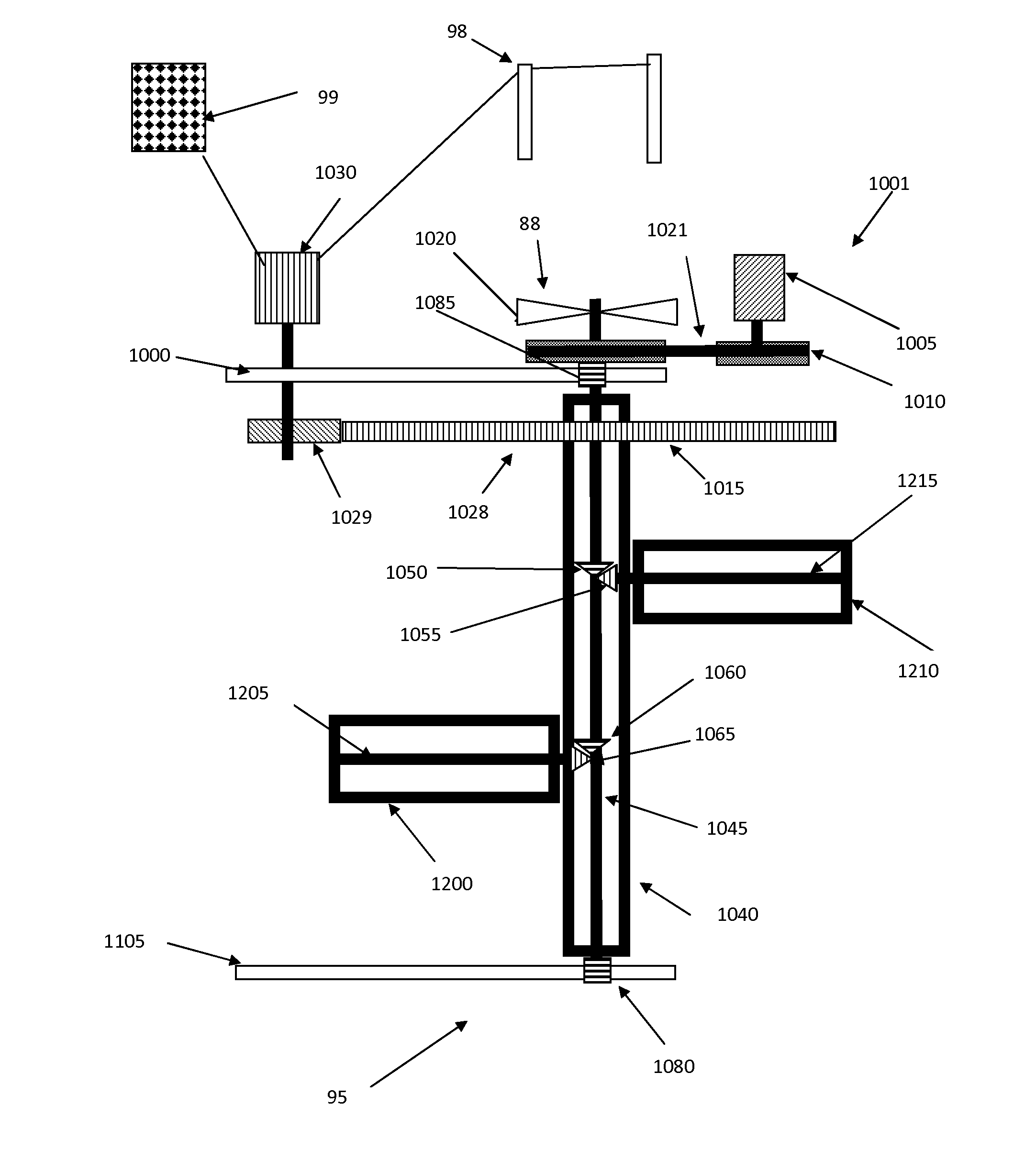
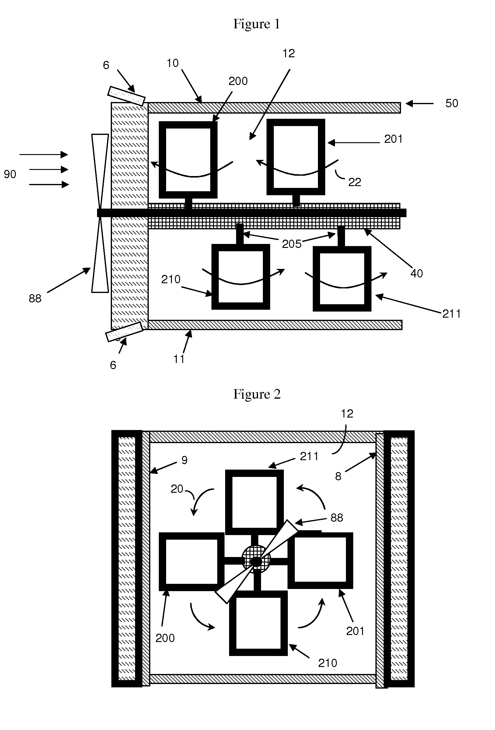
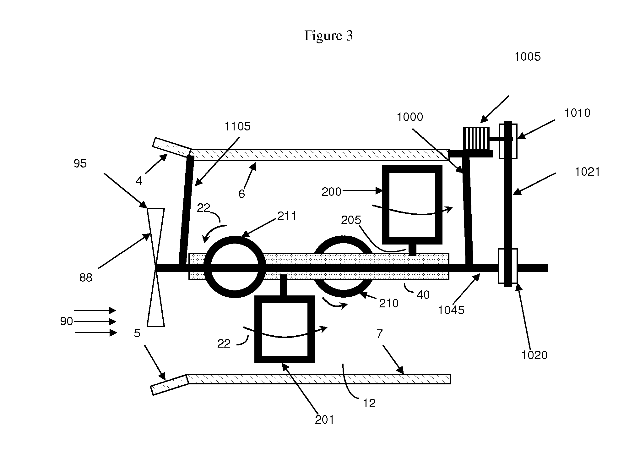
[0049]The invention is based, in part, upon the realization that higher efficiency Magnus force based energy harvesters can be produced by devising methods to better harness the force of the moving fluid to rotate the Magnus cylinder components of the energy harvesters at higher speeds.

[0050]Based upon this insight, the invention then defines the problem to be solved is to devise specific methods to increase the power generation of the Magnus device by utilizing the motion of t...


PUM


Abstract

An energy harvester capable of providing motion from fluid flow, which comprises at least one Magnus cylinder driven to rotate by the movement of the fluid past a fin device. This causes the Magnus cylinder to rotate, and further interactions between the rotating Magnus cylinder and the moving fluid generate a Magnus lifting force. A channel or system may be also provided to direct the fluid flow to the Magnus cylinder. This rotating Magnus cylinder configuration is integrated into a mechanical device that is designed to transfer the Magnus lifting forces into a rotary mechanical motion to drive an electric generator. The device can be utilized in either air or hydraulic environments. A modification of the energy harvester can also be configured to utilize the generated electricity to produce hydrogen for use in fuel cells, or for combustion.

Description

CROSS REFERENCE TO RELATED APPLICATIONS[0001]This application claims the priority benefit of U.S. Provisional Patent Application No. 61 / 276,873 filed Sep. 17, 2009, the contents of which are incorporated herein by reference. This application is a continuation in part of, and claims the priority benefit of, U.S. patent application Ser. No. 12 / 691,951, flied Jan. 22 2010; U.S. patent application Ser. No. 12 / 691,951 in turn claims the priority benefit of U.S. provisional application 61 / 206,044, flied Jan. 26, 2009.BACKGROUND OF THE INVENTION[0002]1. Field of the Invention[0003]The present invention relates to wind and water powered energy harvesters, in particular Magnus type power generators.[0004]2. Description of the Related Art[0005]Although, Savonius turbines have previously been used as effective fluid (e.g. wind, water) motion power generators, this design has the drawback that the Savonius turbine cannot rotate faster than speed of the moving fluid. As a result, Savonius turbin...

Claims


Application Information

Patent Timeline
Patent Type & Authority Applications(United States)
IPC IPC(8): H02K7/00
CPCF03B5/00F03B17/062F03D1/0616F03D3/007Y02E10/74F05B2240/201Y02E10/20Y02E10/28Y02E10/721F05B2210/16Y02E10/72Y02E10/30F03D1/0601
Inventor DOUGLAS, JOEL S.FRENCH, MATTHEWJOHNSON, PAUL RICHARDZIEGLER, AMANDA E.
Owner DOUGLAS JOEL S
Why Eureka
Try Eureka