High humidity gas turbine equipment

a gas turbine and high humidity technology, applied in the direction of machines/engines, mechanical equipment, lighting and heating apparatus, etc., can solve the problems of power generation efficiency reduction, and achieve the effect of suppressing the reduction of power generation efficiency and enhancing cogeneration efficiency

Active Publication Date: 2007-11-29
MITSUBISHI POWER LTD
View PDF11 Cites 13 Cited by
  • Summary
  • Abstract
  • Description
  • Claims
  • Application Information

AI Technical Summary

Benefits of technology

[0006]That is, in the above described prior art, the power generation efficiency is enhanced by utilizing a part of the heat amount recovered from the exhaust gas of the gas turbine for generating the hot water for the humidifier for example, and the cogeneration effect is obtained by utilizing a part of the heat amount recovered from the exhaust gas of the gas turbine for generating the steam to be supplied to the outside. Therefore, for example, if the heat amount utilized for generating the steam to be supplied to the outside is increased with the intention of enhancement of the cogeneration efficiency, for example, the heat amount or the like to be utilized for generating the hot water for the humidifier becomes insufficient, and therefore there is the possibility that the power generation efficiency is reduced.
[0007]An object of the present invention is to provide high humidity gas turbine equipment capable of enhancing cogeneration efficiency while suppressing reduction in power generating efficiency.
[0009]In the present invention, there is provided the first heating device which performs heating by utilizing a factory waste heat medium (mainly a low temperature waste heat medium at about 200° C. or lower) generated in an industrial plant for example, and generates the hot water (for example, the hot water at about 150° C.) for the humidifier. Thereby, factory waste heat can be effectively used. Further, by supplementing the heat amount required for generating the hot water for the humidifier by the factory waste heat, reduction in power generating efficiency can be suppressed without using the exhaust gas of the gas turbine or the like, for example (exhaust gas at about 250° C. or higher, for example). In the present invention, the second heating device which performs heating by utilizing the exhaust gas of the gas turbine and supplies generated steam (or hot water) to a factory or the like is provided. Thereby, the heat amount recovered from the exhaust gas of the gas turbine can be used for generating the steam (or the hot water) to be supplied to the outside without distributing the heat amount for generating the hot water for the humidifier, and the cogeneration efficiency can be enhanced. Accordingly, in the present invention, cogeneration efficiency can be enhanced while reduction in power generating efficiency is suppressed.
[0011]In the present invention, as in the above described (1), there is provided the first heating device which heats water by utilizing a factory waste heat medium (mainly a low temperature waste heat medium at about 200° C. or lower) generated in an industrial plant for example, and generates the hot water (for example, hot water at about 150° C.) for the humidifier. Thereby, factory waste heat can be effectively used. Further, by supplementing the heat amount required for generating the hot water for the humidifier by the factory waste heat from the outside, reduction in power generating efficiency can be suppressed without using, for example, the compressed air discharged from the compressor (compressed air at about 250° C. or higher, for example) or the like. In the present invention, the third heating device which heats water by utilizing the compressed air discharged from the compressor and supplies generated steam (or hot water) to a factory or the like is provided. Thereby, the heat amount recovered from the compressed air discharged from the compressor can be used for generating the steam (or the hot water) to be supplied to the outside without being distributed for generating the hot water for the humidifier, and the cogeneration efficiency can be enhanced. Accordingly, in the present invention, cogeneration efficiency can be enhanced while reduction in power generating efficiency is suppressed.
[0018]Thereby, when switching by the valve means so that the first pipe system is in the communicating state and the second pipe system is in the shutoff state, for example, the second heating device or / and the third heating device can generate steam (or hot water) to be supplied to the outside. On the other hand, when switching by the valve means so that the first pipe system is in the shutoff state and the second pipe system is in the communicating state, for example, the second heating device or / and the third heating device can generate the hot water for the humidifier. Thereby, even when the factory exhaust heat medium cannot be used due to the operating state of a factory for example, the hot water for the humidifier required for power generation can be reliably generated.
[0019]According to the present invention, the cogeneration efficiency can be enhanced while reduction in power generating efficiency is suppressed.

Problems solved by technology

However, the following problem exists in the above described prior art.
Therefore, for example, if the heat amount utilized for generating the steam to be supplied to the outside is increased with the intention of enhancement of the cogeneration efficiency, for example, the heat amount or the like to be utilized for generating the hot water for the humidifier becomes insufficient, and therefore there is the possibility that the power generation efficiency is reduced.

Method used


Image

  • High humidity gas turbine equipment
  • High humidity gas turbine equipment
  • High humidity gas turbine equipment

Examples


Embodiment Construction

[0023]One embodiment of the present invention will now be described with reference to the drawings.

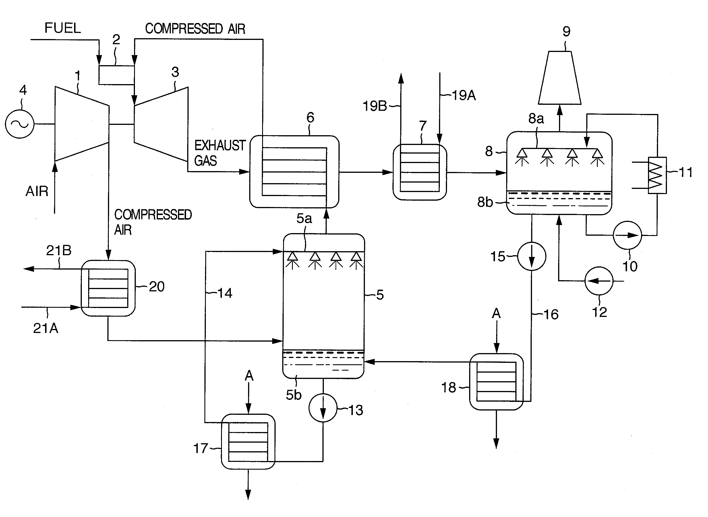
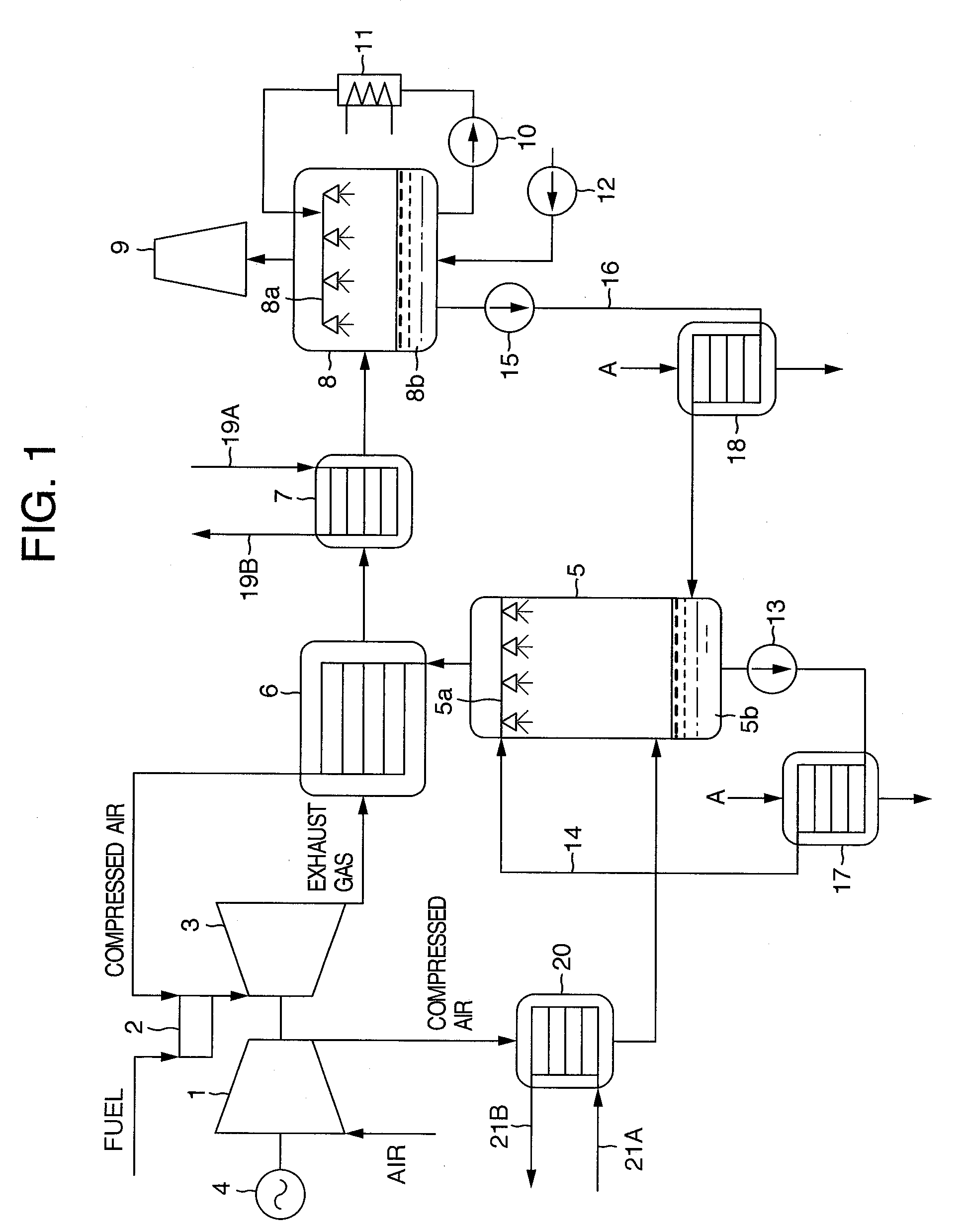
[0024]FIG. 1 is a schematic view showing the configuration of one embodiment of high humidity gas turbine equipment of the present invention.

[0025]In FIG. 1, the high humidity gas turbine equipment includes a compressor 1 which compresses air, a combustor 2 which mixes and combusts the compressed air generated in the compressor 1 and a fuel, a gas turbine 3 which is driven by combustion gas generated in the combustor 2, a generator 4 which generates electric power by drive of the gas turbine 3, a humidifier 5 which brings the compressed air from the compressor 1 in direct contact with hot water and humidifies the compressed air, and a regenerative heat exchanger 6 which heats the compressed air from the humidifier 5 by exhaust gas of the gas turbine 3 and feeds it to the combustor 2. The compressor 1, the gas turbine 3 and the generator 4 are coaxially connected, so that the compressor...


PUM


Abstract

The present invention provides high humidity gas turbine equipment including a compressor compressing air, a combustor combusting the compressed air and a fuel, a gas turbine driven by the combustion gas, a generator driven by the gas turbine to generate power, a humidifier humidifying the compressed air by directly contacting it with hot water, and a regenerative heat exchanger heating the humidified compressed air by exhaust gas of the gas turbine and feeding it to the combustor, heat exchangers generating hot water for the humidifier utilizing a factory exhaust heat medium from the outside, a boiler generating steam to be supplied to the outside utilizing the exhaust gas of the gas turbine, and a boiler generating steam to be supplied to the outside utilizing the compressed air discharged from the compressor.

Description

BACKGROUND OF THE INVENTION[0001]1. Field of the invention[0002]The present invention relates to high humidity gas turbine equipment which humidifies compressed air to be supplied to a combustor, and improves the turbine output and efficiency.[0003]2. Description of related art[0004]High humidity gas turbine equipment includes, for example, a compressor for compressing air, a combustor for mixing compressed air generated by the compressor with a fuel to combust those, a gas turbine driven by combustion gas generated by the combustor, a generator for generating electric power by drive of the gas turbine, a feed water heater for heating water by exhaust gas of the gas turbine, a humidifier for humidifying the compressed air fed from the compressor by means of hot water generated by the feed water heater, and a regenerative heat exchanger for heating the compressed air fed from the humidifier by the exhaust gas of the gas turbine and feeding the compressed air to the combustor (for exa...

Claims


Application Information

Patent Timeline
Patent Type & Authority Applications(United States)
IPC IPC(8): F02C7/10
CPCF02C3/30F02C6/18F02C7/08Y02B30/52F23L15/02F23L2900/00001Y02E20/14F22B1/1807Y02E20/34Y02P80/10Y02P80/15
Inventor SASAKI, KENJINOGUCHI, YOSHIKI
Owner MITSUBISHI POWER LTD
Why Eureka
Try Eureka