Fluid dynamic bearing with an immiscible fluid barrier

a dynamic bearing and fluid barrier technology, applied in the field of hard disk drive development, can solve the problems of reducing affecting the elasticity of the surface, and the design of the ball bearing cannot overcome the nrro problem, etc., to achieve the effect of reducing the surface elasticity, inhibiting mass transfer, and preventing vaporization free energy

Active Publication Date: 2013-12-31
WESTERN DIGITAL TECH INC
View PDF15 Cites 1 Cited by
  • Summary
  • Abstract
  • Description
  • Claims
  • Application Information

AI Technical Summary

Benefits of technology

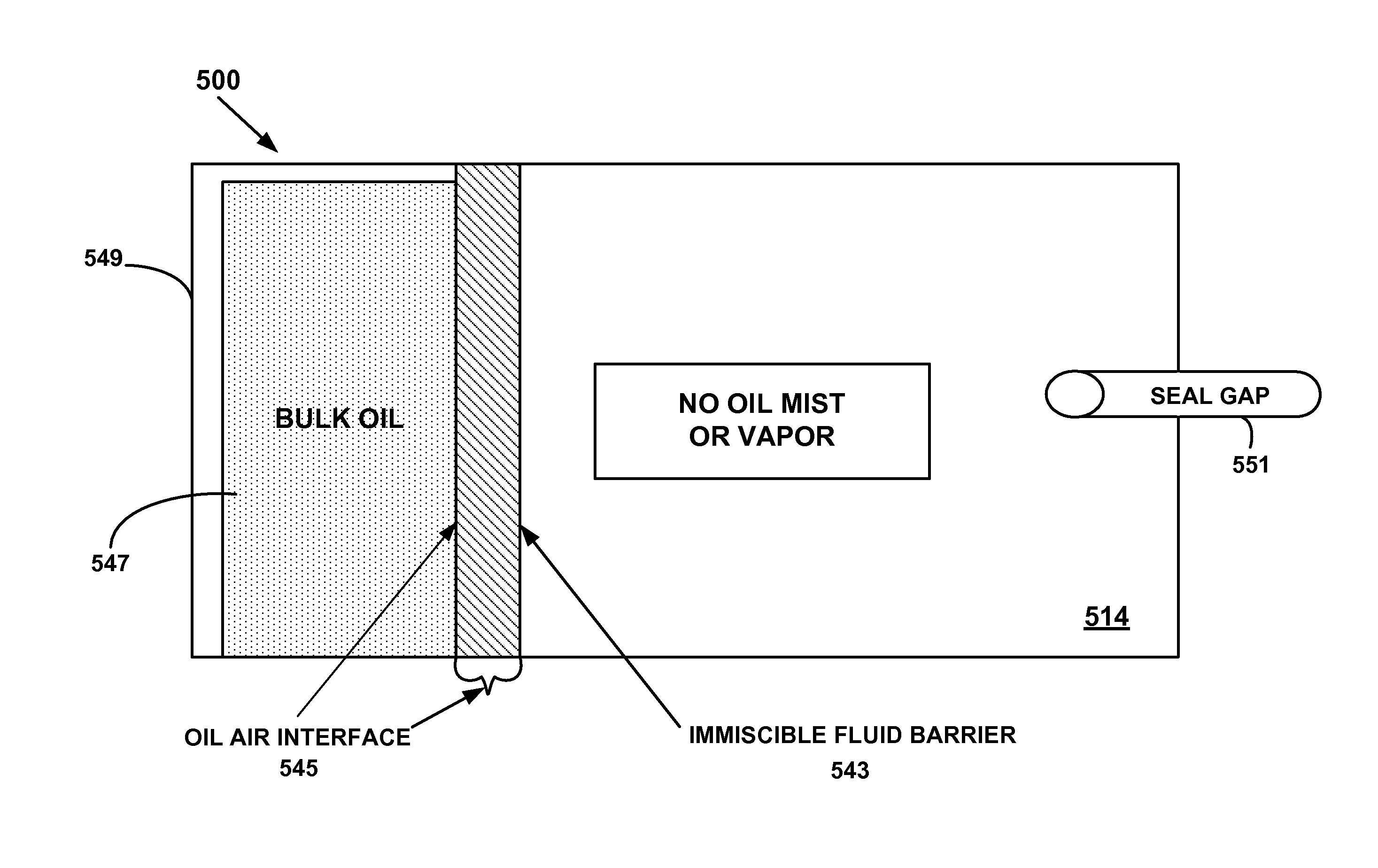
[0013]The surface layer between the oil and the air inhibits mass transfer of the oil molecules into the vapor by presenting an additional barrier to the vaporization free energy. To reduce oil mist, the surface layer also reduces the surface elasticity. In one embodiment, nonfunctional perfluoropolyethers may be utilized. In an alternate embodiment, a narrow molecular weight fraction with a much lower vapor pressure than the fluid dynamic bearing oil may be used to provide evaporation and mist control.

Problems solved by technology

Ball bearing motors produce larger NRRO due to the mechanical contact with the inherent defects found in the geometry of the race ball interface and the lubricant film.
There is an upper limit beyond which the ball bearing design can no longer overcome the NRRO problem at the higher areal densities.
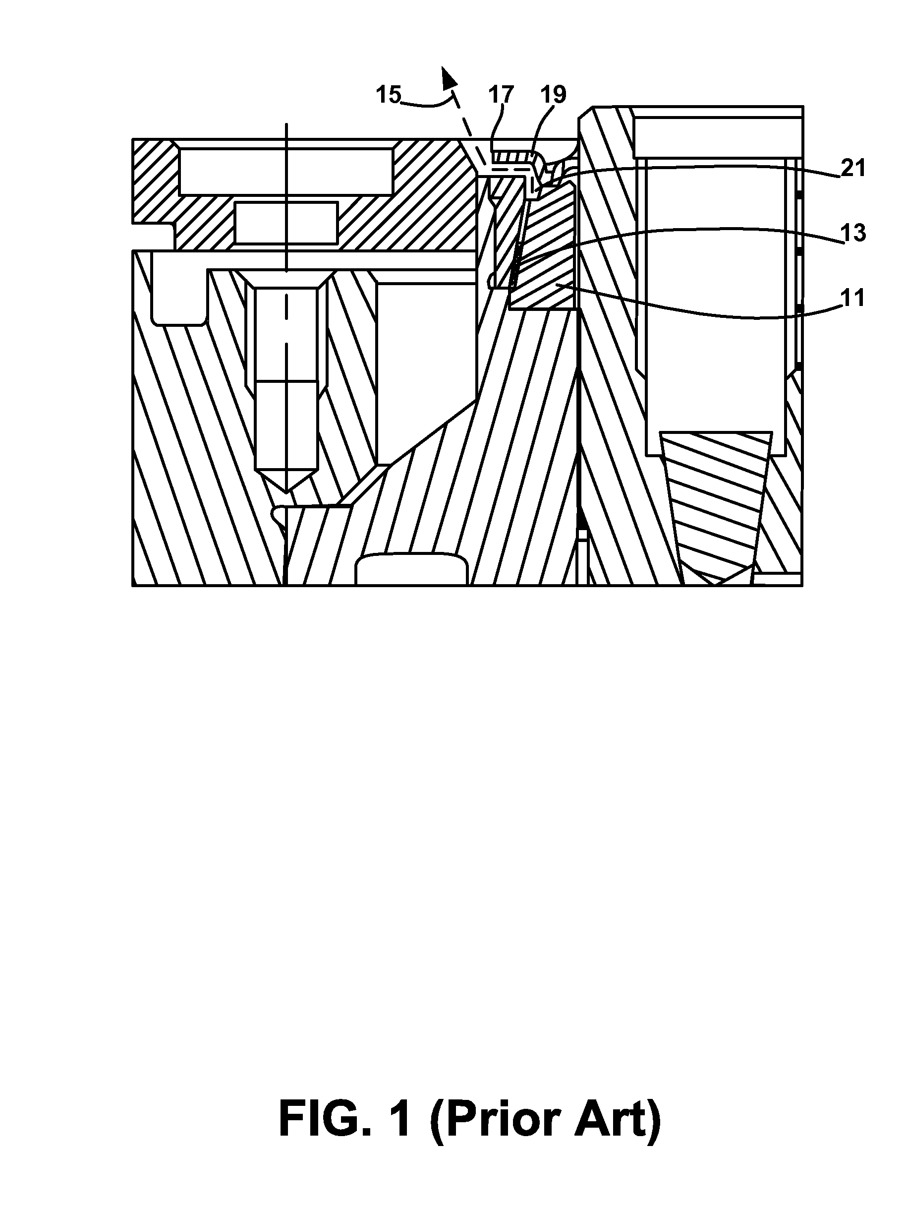
However, problems with FDBs are the contamination of the head disk enclosure with the lubrication and loss of fluid within the bearing.
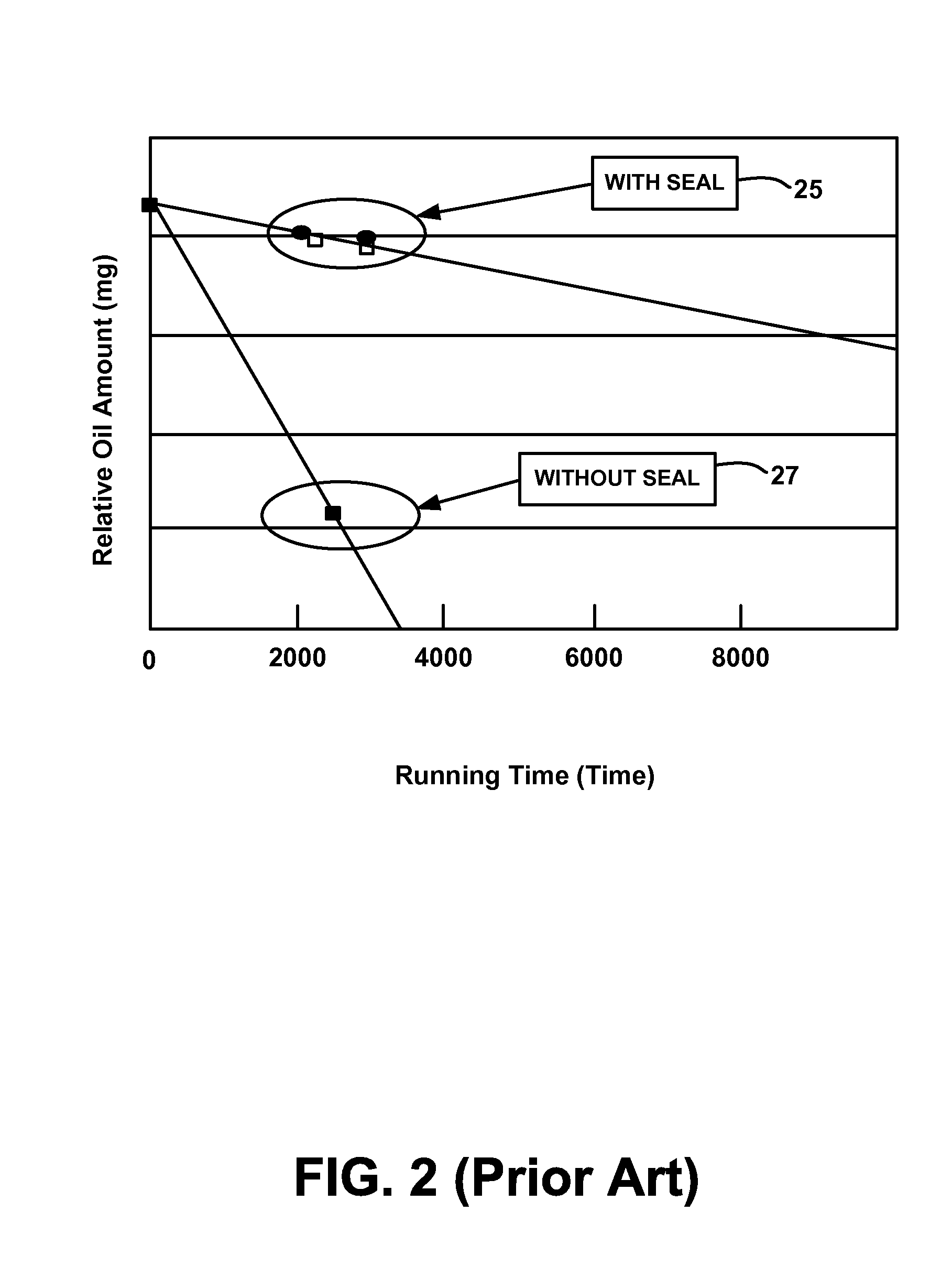
For example, significant oil loss is observed from server class fluid bearing disk drive motors during accelerated life tests at elevated temperature.
However, that option is a less desirable solution since oil with lower volatility has a higher viscosity that can result in a 30% increase in power consumption and difficulty in cold starts.
Hydrocarbon surfactants cannot readily form a low surface tension monolayer on the surface of another hydrocarbon, so these methods have not been successfully applied to suppress oil evaporation.
However, a foam will not work in the fluid bearing motor of a disk drive because of the very small annular space limitations and because foams are not stable for the long life required of magnetic storage devices.
Although polymers increase the viscosity of the fluid bearing oil, it does not provide enough suppression of evaporation.
Thus, none of the known solutions for suppressing the evaporation of fuel or oil are sufficient to provide an integral evaporation barrier in the presence of interfacial shear flow that is present on the oil meniscus in a disk drive fluid bearing spindle motor.

Method used


Image

  • Fluid dynamic bearing with an immiscible fluid barrier
  • Fluid dynamic bearing with an immiscible fluid barrier
  • Fluid dynamic bearing with an immiscible fluid barrier

Examples


Embodiment Construction

[0023]Reference will now be made in detail to the alternative embodiment(s) of the present invention. While the invention will be described in conjunction with the alternative embodiment(s), it will be understood that they are not intended to limit the invention to these embodiments. On the contrary, the invention is intended to cover alternatives, modifications and equivalents, which may be included within the spirit and scope of the invention as defined by the appended claims.

[0024]Furthermore, in the following detailed description of the present invention, numerous specific details are set forth in order to provide a thorough understanding of the present invention. However, it will be recognized by one of ordinary skill in the art that the present invention may be practiced without these specific details. In other instances, well known methods, procedures, components, and circuits have not been described in detail as not to unnecessarily obscure aspects of the present invention.

[...


PUM

PropertyMeasurementUnit
thickaaaaaaaaaa
thickaaaaaaaaaa
magneticaaaaaaaaaa

Abstract

A fluid dynamic bearing with an immiscible fluid barrier deposited on the bearing oil is disclosed. One embodiment provides the fluid dynamic bearing having a seal gap to define a seal cavity. The seal cavity is filled with the bearing oil for lubricating the fluid dynamic bearing. The immiscible fluid is disposed on the bearing oil to prevent the bearing oil from evaporating from the seal cavity. In one embodiment, the immiscible fluid is insoluble in the bearing oil.

Description

TECHNICAL FIELD[0001]The present invention relates to the field of hard disk drive development, and more particularly to resolving particulate contamination and fluid loss in a fluid dynamic bearing.BACKGROUND ART[0002]Direct access storage devices (DASD) have become part of every day life, and as such, expectations and demands continually increase for greater speed for manipulating data and for holding larger amounts of data. To meet these demands for increased performance, the mechanical assembly in a DASD device, specifically the Hard Disk Drive (HDD) has undergone many changes.[0003]In operation, the hard disk is rotated at a set speed via a spindle motor assembly having a central drive hub. Additionally, there are tracks evenly spaced at known intervals across the disk. When a request for a read of a specific portion or track is received, the hard disk aligns the head, via the arm, over the specific track location and the head reads the information from the disk. In the same ma...

Claims


Application Information

Patent Timeline
Patent Type & Authority Patents(United States)
IPC IPC(8): G11B17/02
CPCF16C33/74G11B19/2036F16C2370/12F16C33/10
Inventor KARIS, THOMAS E.SCHIRLE, NEAL B.SHIDA, KUNIHIRO
Owner WESTERN DIGITAL TECH INC
Why Eureka
Try Eureka