System for ejecting a spin-stabilized space flying body

Inactive Publication Date: 2005-03-03
BANK CHRISTIAN +1
View PDF7 Cites 5 Cited by
  • Summary
  • Abstract
  • Description
  • Claims
  • Application Information

AI Technical Summary

Benefits of technology

[0011] to construct such an ejection mechanism so that ri

Problems solved by technology

All of the above described conventional ejection systems have a substantial disadvantage of a relatively high weight and a complex construction.
Another disadvantage is particularly seen in the use of explosives in manned orbital missions and/or the use of strong spiral springs.
Explo

Method used


Image

  • System for ejecting a spin-stabilized space flying body
  • System for ejecting a spin-stabilized space flying body
  • System for ejecting a spin-stabilized space flying body

Examples


Embodiment Construction

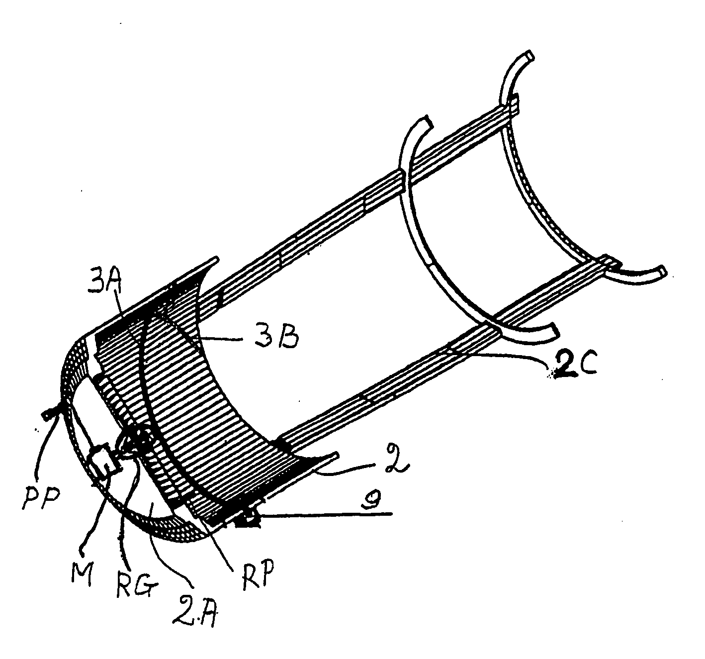
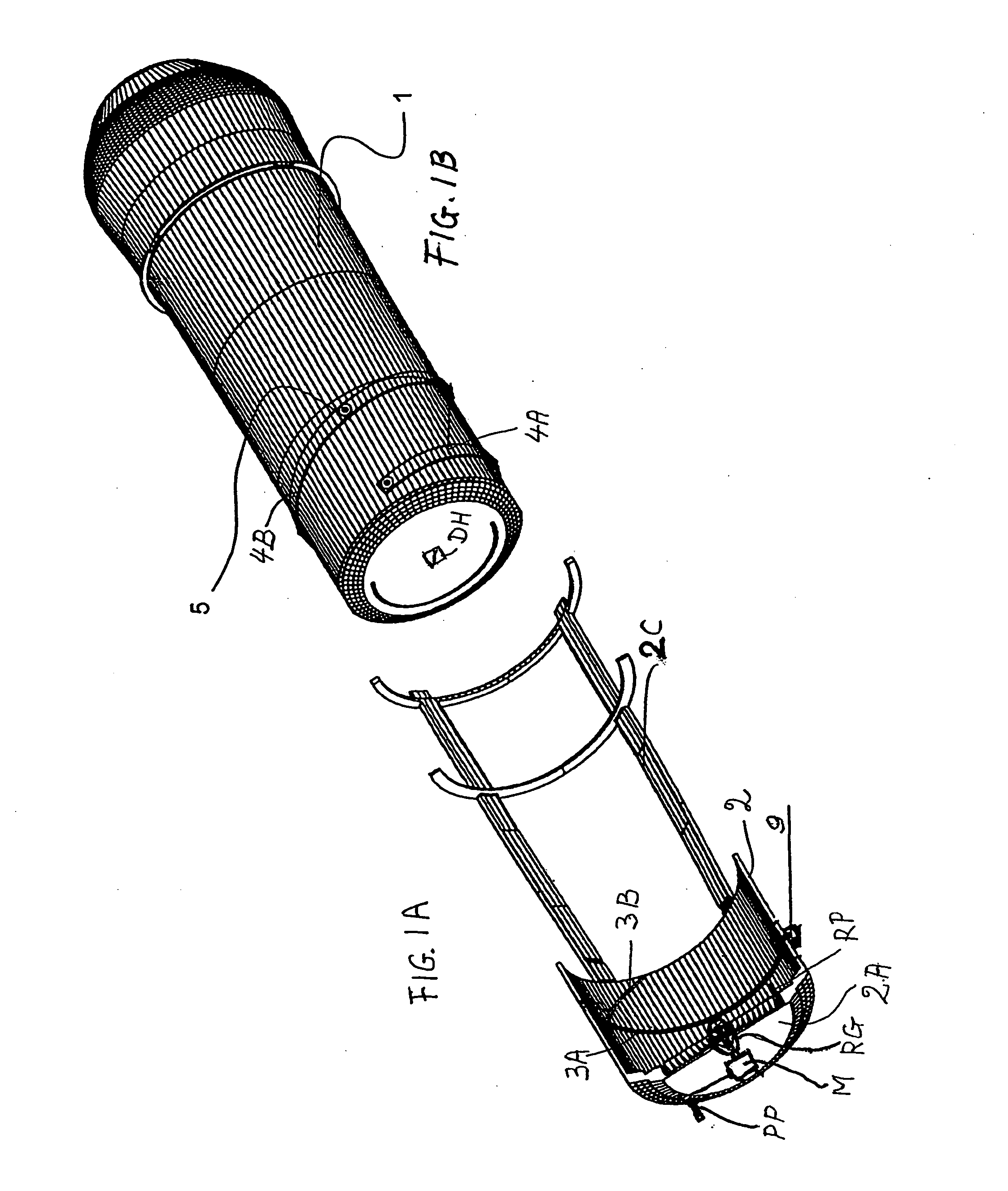
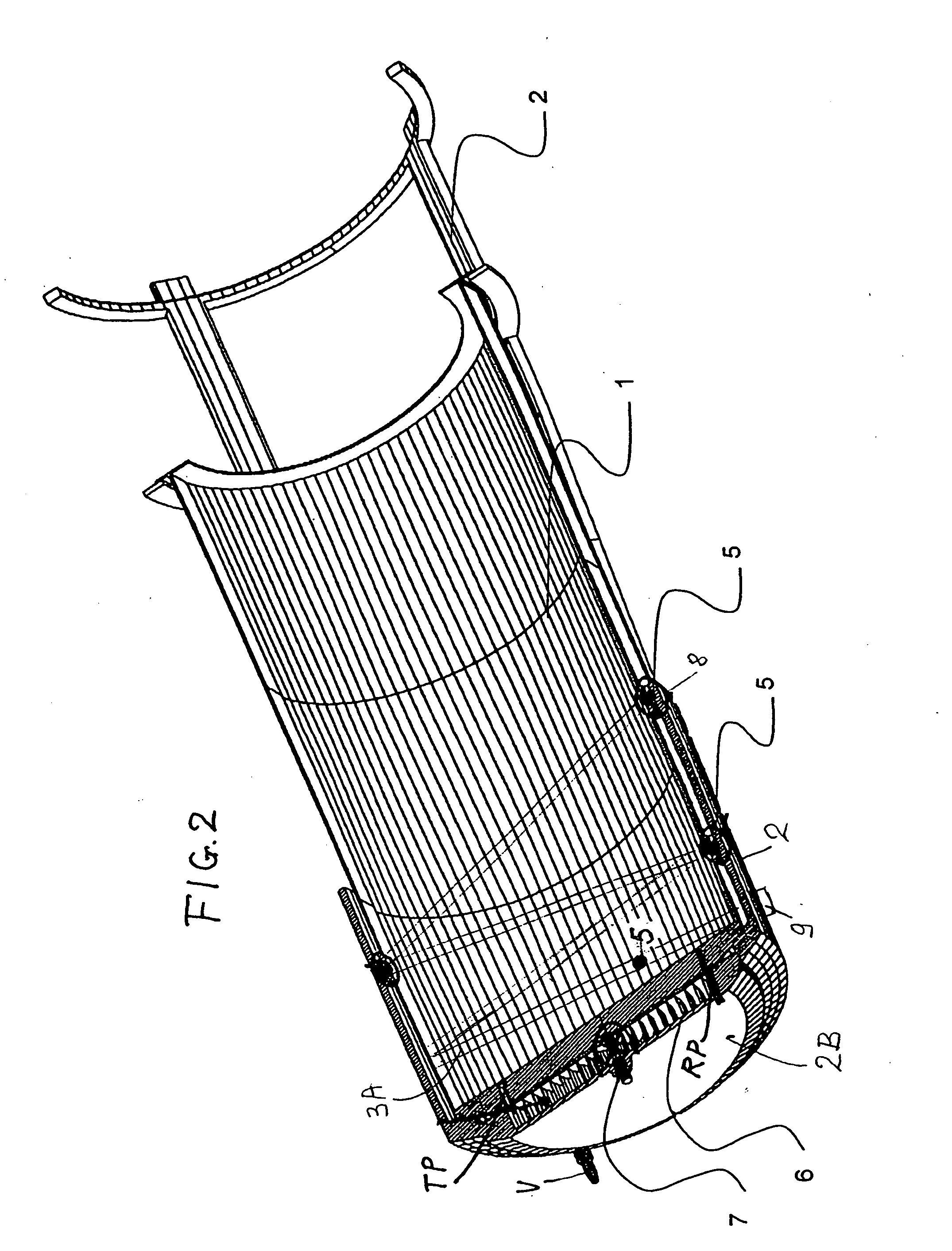
[0025]FIG. 1A shows an ejection tube 2 with a bottom chamber 2A from which a cover 2B shown in FIG. 2 has been removed. For weight reduction purposes, the ejecting tube is constructed as short as possible. For the same purpose a guide frame 2C is connected to the ejecting tube 2. The ejection tube 2 has an inwardly facing tube wall provided with a guide track or groove section 3A and a further guide track or groove section 3B. The flying body 1 comprises a corresponding first guide track or groove section 4A and a second guide track or groove section 4B. A drive hole DH for engagement by a withdrawable and rotatable drive pin of a motor M or of a reduction gear RG is provided in the bottom of the flying body 1 as shown in FIG. 1B.

[0026] Guide balls or spheres 5 are movable in the guide tracks or grooves 3A, 3B and 4A and 4B. The guide ball 5 in FIG. 1B is shown only for illustration purposes because according to the invention the balls 5 are retained in the ejecting tube 2 as will ...


PUM


Abstract

A spacecraft or space flying body is spin-stabilized as the body is expelled from an ejection tube, for example from a larger spacecraft. For imposing spin stabilization on the flying body, a guide groove is provided between an outer wall of the flying body and an inner wall of the ejection tube. The guide groove has at least partly a helical slope. Guide spheres or balls travel in the guide groove as the flying body is driven by a drive, such as a spiral spring or an electric motor, out of the ejecting tube.

Description

PRIORITY CLAIM [0001] This application is based on and claims the priority under 35 U.S.C. §119 of German Patent Application 103 37 973.8, filed on Aug. 19, 2003, the entire disclosure of which is incorporated herein by reference. FIELD OF THE INVENTION [0002] The invention relates to launching a spin-stabilized flying body capable of traveling in outer space, either manned or unmanned, either propelled or unpropelled. BACKGROUND INFORMATION [0003] It is known to eject space flying bodies from a spacecraft, particularly a space station. A drive imposes a driving force on the body to be ejected. The driving force comprises a rotational component for imposing a spin on the flying body as the flying body is ejected and a translatory component for propelling the flying body in a travel direction out of an ejecting tube. [0004] Heretofore ejecting mechanisms for such flying bodies have been developed for use in satellites, for example in so-called spy satellites for the ejection of retur...

Claims


Application Information

Patent Timeline
IPC IPC(8): B64G1/64F41A21/16F41B7/00F42B10/26F42B14/02
CPCB64G1/645F41A21/16F42B14/02F42B10/26F41B7/00
Inventor BANK, CHRISTIANKOLLOGE, HANS-GEORG
Owner BANK CHRISTIAN
Why Eureka
Try Eureka