
Anti-collision device for plasma vertical cutting gun

a cutting gun and anti-collision technology, which is applied in the direction of plasma welding apparatus, heat treatment apparatus, manufacturing tools, etc., can solve the problems of insufficient protection and failure to meet the operating requirements, and achieve the effects of reducing the shortcomings of conventional anti-collision devices, excellent safety protection, and flexible structur

Active Publication Date: 2014-01-07
WUHAN FARLEYLASERLAB CUTTING SYST ENG
View PDF8 Cites 1 Cited by
  • Summary
  • Abstract
  • Description
  • Claims
  • Application Information

AI Technical Summary

Benefits of technology

[0008]In view of the above-described problems, it is one objective of the invention to provide a full-featured and reasonably-structured anti-collision device for a plasma vertical cutting gun to eliminate shortcomings of conventional anti-collision devices and make them to be more flexible, stable, and have excellent safety protection.
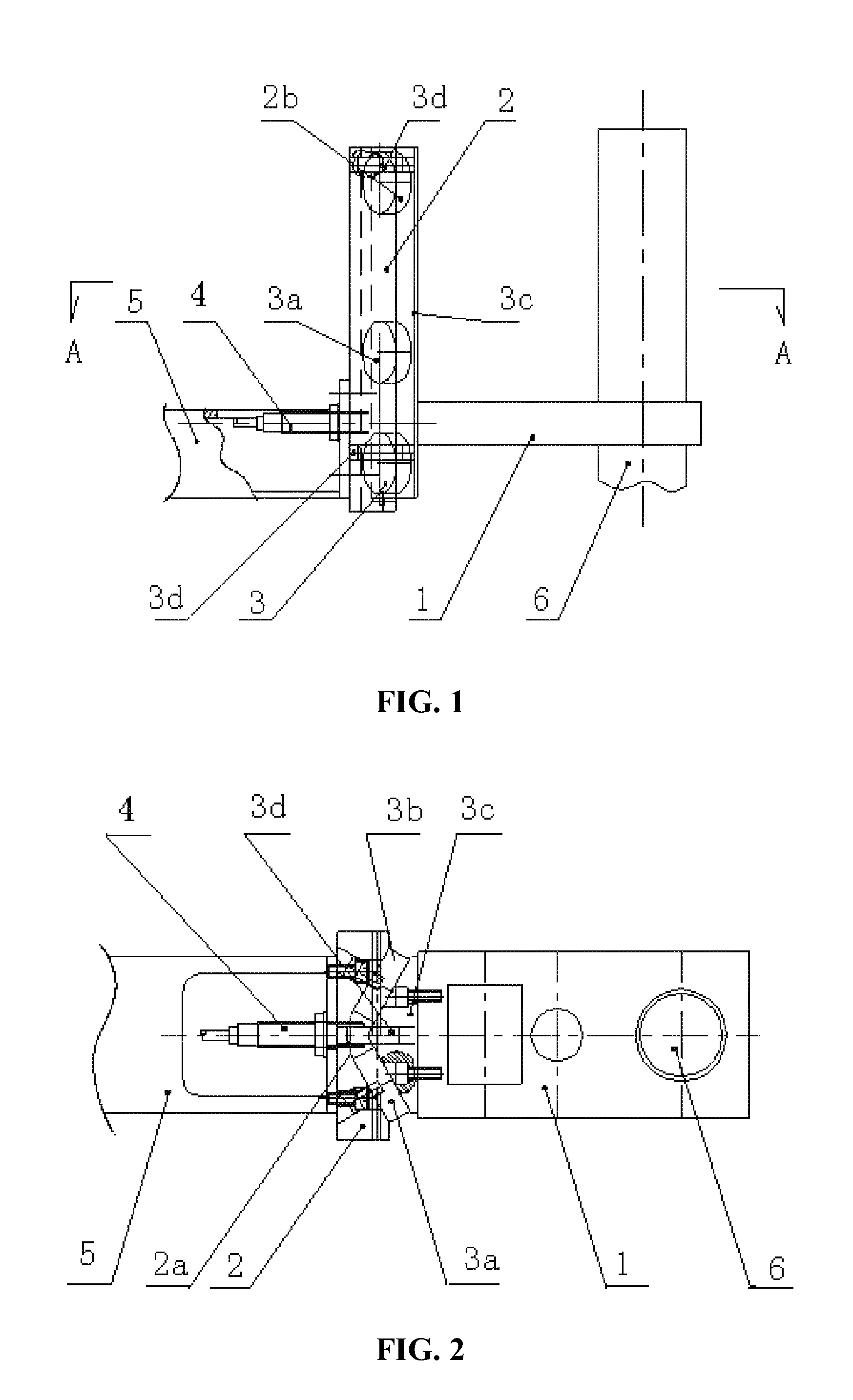
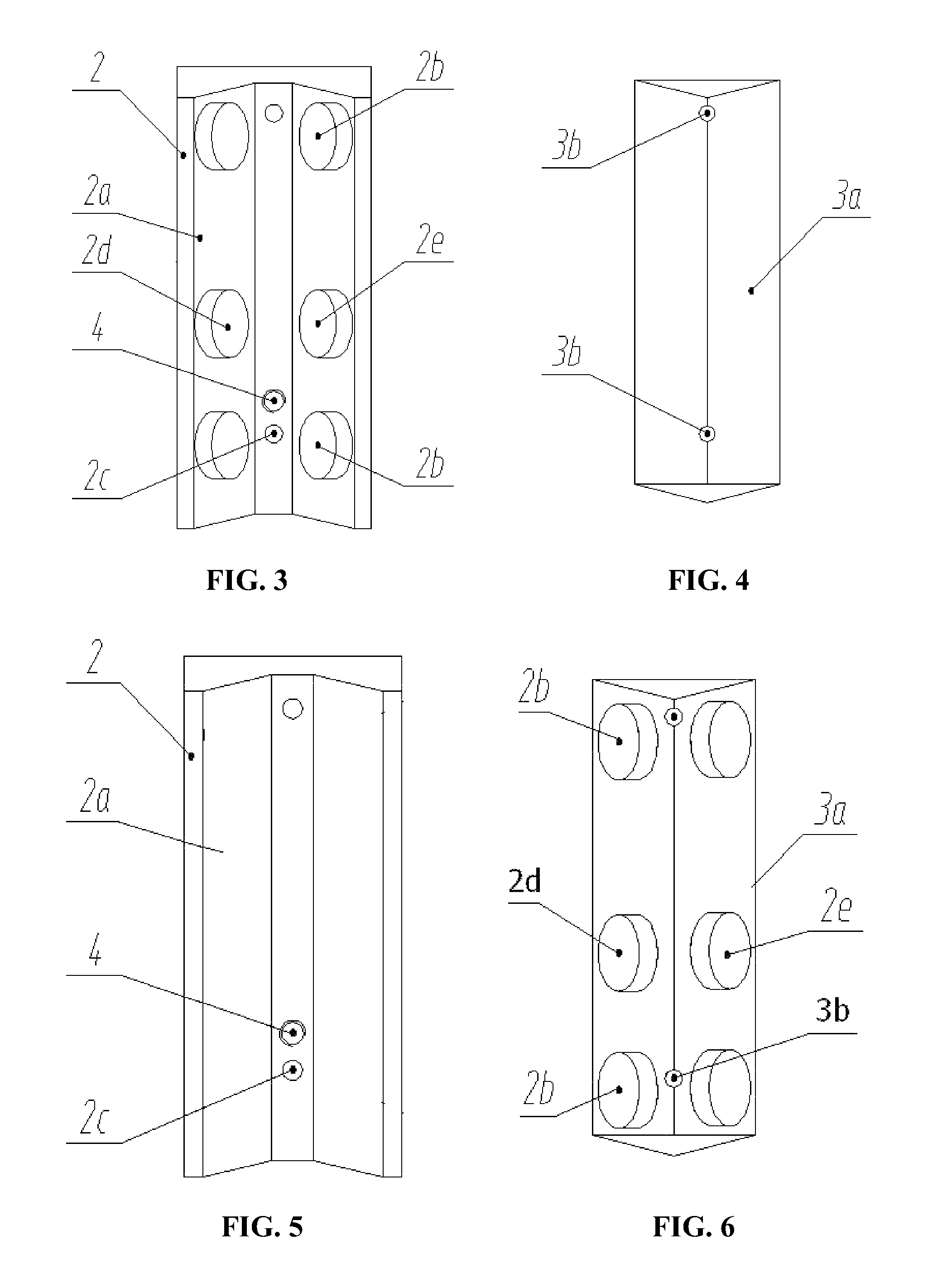
[0024]In a class of this embodiment, the two magnets on the isosceles-triangle cushion block are symmetrically fixed to vertical central parts of the two inclined planes of the isosceles-triangle cushion block; and the vertical upper and lower portions of the two inclined planes of the isosceles-triangle cushion block are respectively fixed with the nonmagnetic stable block with the same thickness as the magnet, thereby leveling the upper and lower gaps between the isosceles-triangle cushion block and the concave support plate.
[0026]Advantages of the invention are summarized below: the anti-collision device of the cutting gun of the invention has the advantages of comprehensive functions, convenient installation, reasonable structure, and short response time in case of impact. The device has excellent safety protection ability to shut down immediately.

Problems solved by technology

Conventional anti-collision devices of cutting guns adopt a rigid connection style, which has a bigger impact on the cutting guns and the protection is insufficient; the response lags when a problem occurs, thus failing to meet the operating requirement.

Method used


Image

  • Anti-collision device for plasma vertical cutting gun
  • Anti-collision device for plasma vertical cutting gun
  • Anti-collision device for plasma vertical cutting gun

Examples


Embodiment Construction

[0033]The invention is explained in further detail below with the aid of the embodiments and attached drawings:

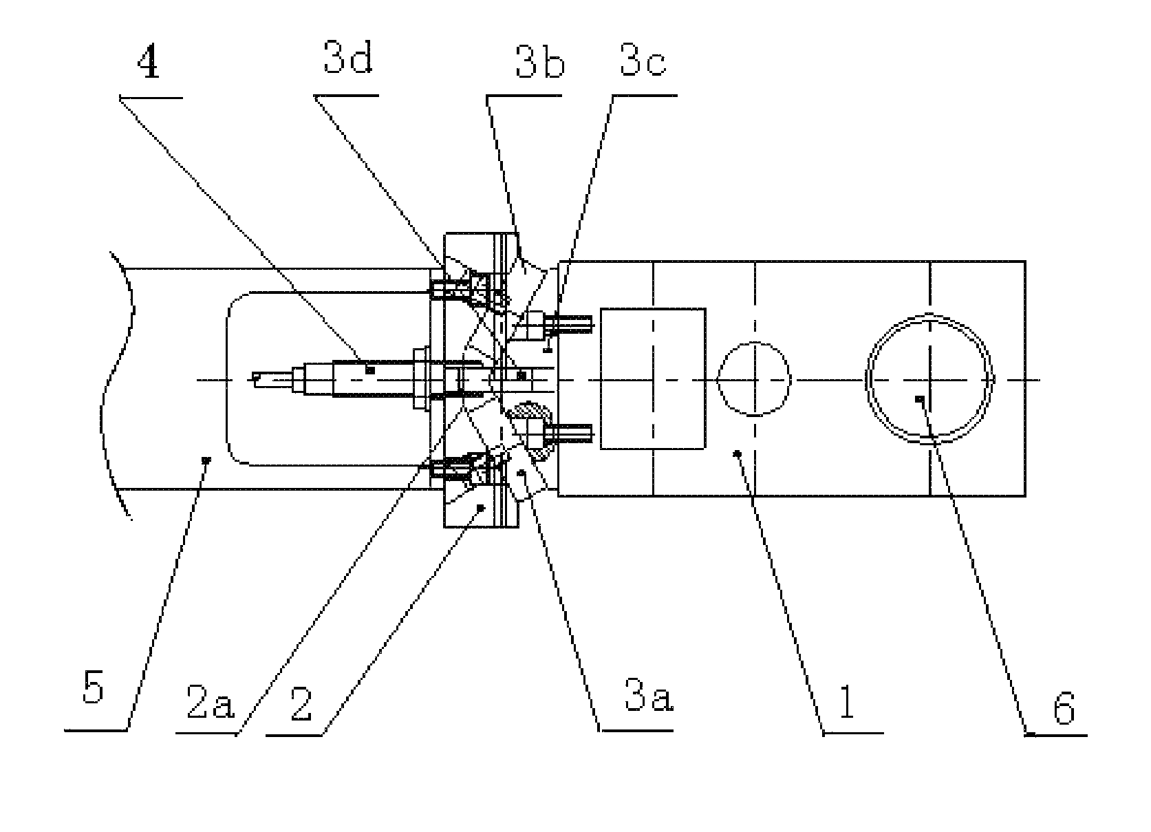
[0034]As shown in FIGS. 1-2, an anti-collision device for a plasma vertical cutting gun comprises a lifting frame of a plasma cutting machine 5, a fixing plate of a cutting gun 1, a proximity switch 4, a connection mechanism 3 mounted between the lifting frame of the plasma cutting machine 5 and the fixing plate of the cutting gun 1. The fixing plate of the cutting gun 1 is fixed on the connection mechanism 3. The connection mechanism 3 comprises an isosceles-triangle cushion block 3a connected with the cutting gun fixing panel 1. The upper and lower portions of the isosceles-triangle cushion block 3a are respectively arranged with a locating pin 3b. The proximity switch 4 is mounted on a concave support plate 2 connecting with the lifting frame of the plasma cutting machine 5. A detection head of the proximity switch 4 aligns with the apical angle of the isosceles-triangle...


PUM

PropertyMeasurementUnit
ferromagneticaaaaaaaaaa
inclined angleaaaaaaaaaa
apical angleaaaaaaaaaa

Abstract

An anti-collision device for a plasma vertical cutting gun including a lifting frame of a plasma cutting machine; a connection mechanism; a fixing plate of a cutting gun fixed on the connection mechanism; a concave support plate connected with the lifting frame of the plasma cutting machine; and a proximity switch mounted on the concave support plate. The connection mechanism is mounted between the lifting frame of the plasma cutting machine and the fixing plate of the cutting gun. A contact surface between the connection mechanism and the concave support plate matches. One side of a joint plane between the connection mechanism and the concave support plate is of ferromagnetic materials and the other side is provided with a magnet, thereby attracting each other to realize a magnetic connection. The anti-collision device has comprehensive functions, convenient installation, reasonable structure, and short response time in case of impact.

Description

CROSS-REFERENCE TO RELATED APPLICATIONS[0001]This application is a continuation of International Patent Application No. PCT / CN2010 / 072840 with an international filing date of May 17, 2010, designating the United States, now pending, and further claims priority benefits to Chinese Patent Application No. 200920087032.4 filed Jun. 30, 2009. The contents of all of the aforementioned applications, including any intervening amendments thereto, are incorporated herein by reference.BACKGROUND OF THE TECHNOLOGY[0002]1. Field of the Invention[0003]The invention relates to an anti-collision device for a plasma vertical cutting gun and the anti-collision device is a supporting device of a numerical control (NC) plasma cutting machine.[0004]2. Description of the Related Art[0005]Plasma cutting technique is a technology using high-speed ejected ionized gas blown out of a compressed gas outlet to realize a cutting effect. The principle is that the ionized gas having high-speed, high temperature, h...

Claims


Application Information

Patent Timeline
Patent Type & Authority Patents(United States)
IPC IPC(8): B23K10/00H05H1/36
CPCB23K10/00B23K10/006
Inventor XIONG, YANJUNGAO, WEIYE, SONGPINGDONG, JIEWANG, LIN
Owner WUHAN FARLEYLASERLAB CUTTING SYST ENG
Learn More