Phase and frequency locked magnetron

a phase and frequency locked, magnetron technology, applied in the direction of magnetrons, electric discharge tubes, transit-tube coupling devices, etc., can solve the problems of reducing efficiency, reducing production and operation, and high-power rf systems being expensive to build and opera

Inactive Publication Date: 2014-01-07
MUONS
View PDF8 Cites 4 Cited by
  • Summary
  • Abstract
  • Description
  • Claims
  • Application Information

AI Technical Summary

Problems solved by technology

High-power RF systems are expensive to build and costly to operate because of their inefficiency and unreliability, primarily due to the distribution of high power levels over large distances.
The RF power gun klystrons is usually distributed to multiple strings of cavities through high-power waveguide systems, which are expensive to produce and to operate, because of reduced efficiency and lower reliability of the distribution system.
In such systems, the final power output stage is an amplifier; this gives inherently good phase and frequency control from a low-level RF reference signal, at the cost of significantly reduced efficiency.
Unfortunately, none of those techniques have proven to be sufficiently stable, flexible, and accurate enough for use in particle accelerators.

Method used


Image

  • Phase and frequency locked magnetron
  • Phase and frequency locked magnetron
  • Phase and frequency locked magnetron

Examples


Embodiment Construction

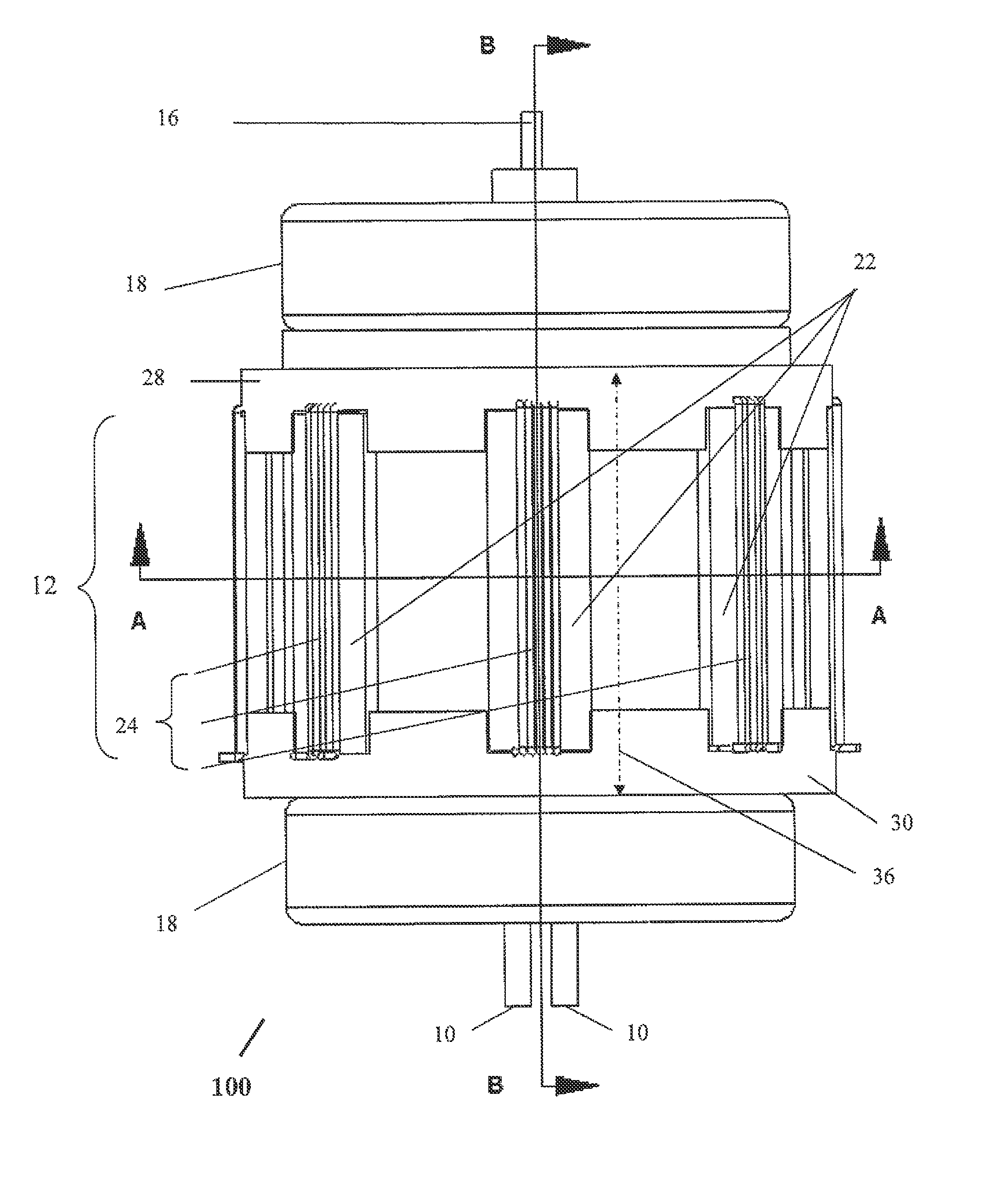
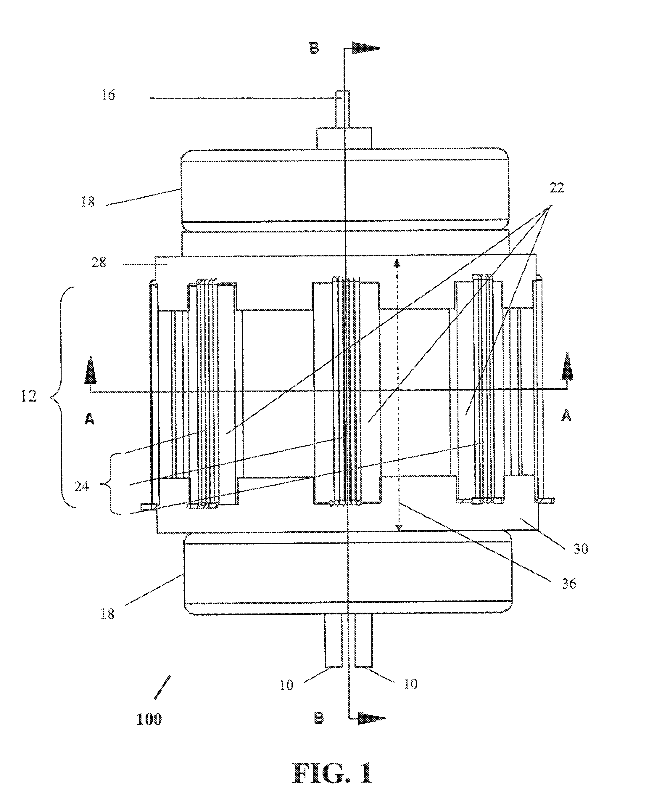
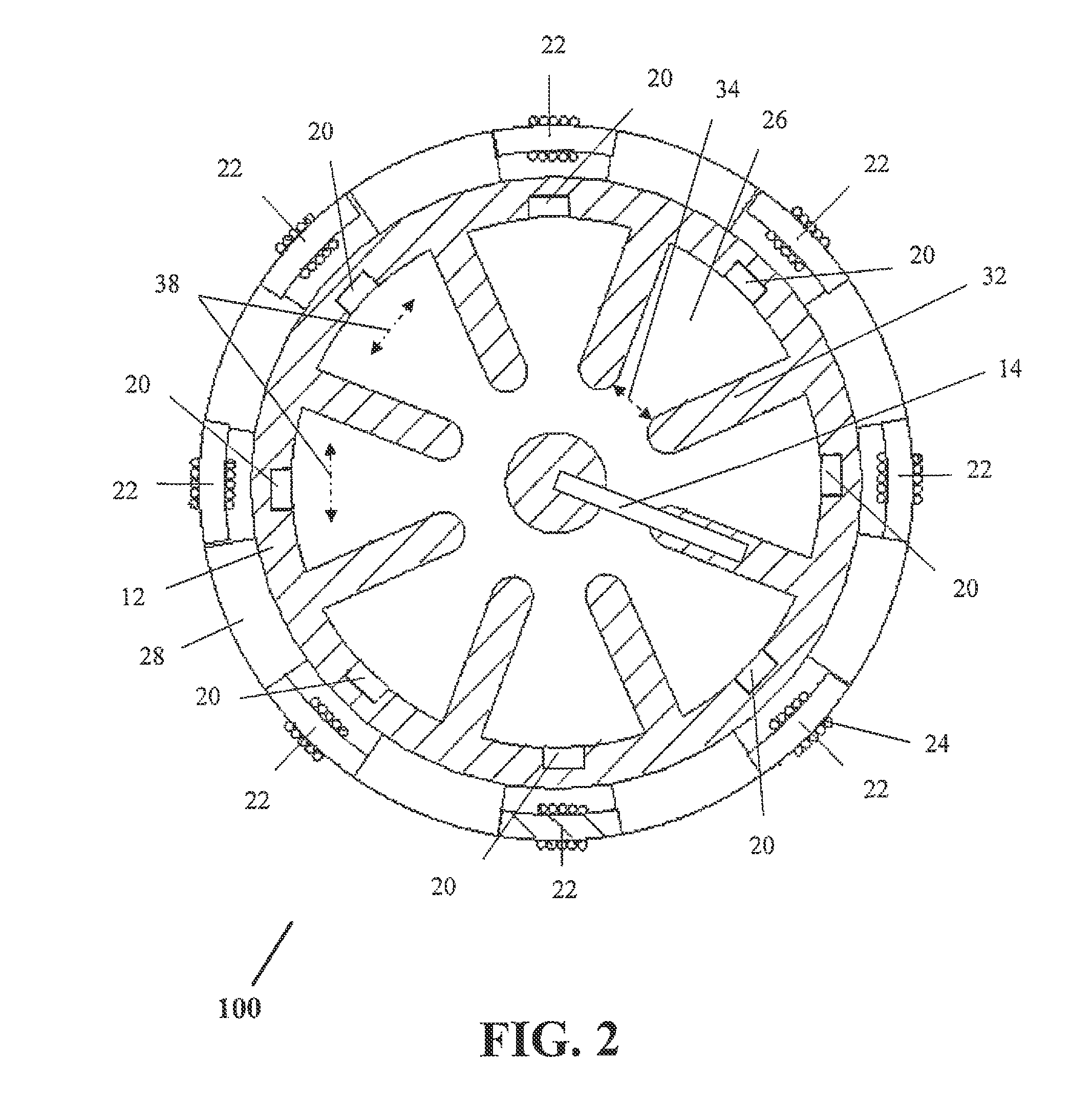
[0029]The present device uses a different approach, and is based on a variable-permeability material in the resonant structures of a magnetron. The permeability of a material is its degree of internal magnetization in response to an applied magnetic field. When a permeable material is placed in or around an RF resonant structure, the permeability of the material affects the resonant frequency of the structure due to the material's response to the rapidly varying RF magnetic field. Some materials, such as ferrite or Yttrium Iron Garnet, exhibit a permeability that can be varied by application of a magnetic field that is orthogonal to the RF magnetic field. This permits a bias magnetic field to control the resonant frequency of the structure.

[0030]In order to sustain oscillations in a resonant circuit, it is necessary to continuously input energy in the correct phase.

[0031]In accordance with the present invention, there is provided an apparatus to improve the operation of a convention...


PUM


Abstract

A magnetron of improved performance capable of stabilizing the frequency and phase of magnetron output for use in particle accelerators and other applications. Thin variable-permeability blocks are attached inside the resonant anode structures of a standard magnetron design. A variable bias electromagnet, with field orthogonal in direction to the RF magnetic field, is used to vary the permeability of each block and therefore the resonant frequency of each anode structure. An electronic feedback control circuit adjusts the bias magnetic fields to lock in the frequency and phase of the magnetron output to an external low-level reference signal. Such devices may be used to provide synchronized high-power RF to many locations (e.g. the RF cavities of a particle accelerator), while requiring the distribution only of electrical power and an appropriate low-level RF reference signal.

Description

CROSS-REFERENCE TO RELATED APPLICATION[0001]The present application claims the benefit of U.S. Provisional Patent Application No. 61 / 253,470, filed Oct. 20, 2009, the entire disclosure of which is hereby incorporated by reference.STATEMENT REGARDING FEDERALLY SPONSORED RESEARCH OR DEVELOPMENT[0002]The U.S. Government has a paid-up license in this invention and the right in limited circumstances to require the patent owner to license others on reasonable terms as provided for by the terms of USDOE Contract No. DE-AC05-84-ER-40150 and STTR Grant DE-SC0002766.FIELD OF THE INVENTION[0003]The present invention relates to microwave power generation for diverse purposes and, more particularly, to those applications requiring precise control of the phase and frequency of the output power, such as for radiofrequency (RF) devices used in particle accelerators.BACKGROUND OF THE INVENTION[0004]High-power RF systems are expensive to build and costly to operate because of their inefficiency and u...

Claims


Application Information

Patent Timeline
Patent Type & Authority Patents(United States)
IPC IPC(8): H01J25/50
CPCH01J25/587H01J25/50
Inventor NEUBAUER, MICHAELPOPOVIC, MILORADJOHNSON, ROLLAND P.
Owner MUONS
Why Eureka
Try Eureka