Device for sealing and inflating inflatable object

a technology for sealing and inflating inflatable objects, which is applied in the direction of vehicle maintenance, liquid handling, packaging goods type, etc., can solve the problems of not being easily connected or coupled to the air compressor device, sealing preparation may not be easily forced to flow upward and out, and pressure tight containers may not be easily removed from the air compressor. , to achieve the effect of quick coupling, attaching and securing, and effectively providing sealing

Active Publication Date: 2014-01-14
CHOU WEN SAN
View PDF21 Cites 31 Cited by
  • Summary
  • Abstract
  • Description
  • Claims
  • Application Information

AI Technical Summary

Benefits of technology

[0014]The primary objective of the present invention is to provide a sealing and inflating assembly comprising an air compressing device including an improved tire repairing container for quickly coupling and attaching and securing to an outlet tube of the air compressor and for quickly disengaging from the air compressor and for allowing the tire sealing preparation to be effectively supplied to seal and inflate the inflatable objects.
[0015]The other objective of the present invention is to provide a sealing and inflating assembly for sealing and inflating an inflatable object comprising a tire repairing container that may be easily and quickly and changeably attached and secured to the outlet tube of the air compressor.
[0017]The still further objective of the present invention is to provide a sealing and inflating assembly for sealing and inflating an inflatable object comprising a control valve for preventing the sealing preparation from flowing into the inflatable objects inadvertently.

Problems solved by technology

However, the pressure tight container and the pressurized air cartridge are coupled together with a shut off valve, a gas outlet, a gas inlet and may not be easily disengaged from each other, and an outlet valve and an additional riser tube are further required to be attached or mounted to the upper portion of the pressure tight container for allowing the sealing preparation to be selectively supplied to seal and inflate the inflatable objects, but may not be easily connected or coupled to the air compressor devices.
In addition, the sealing preparation may not be easily forced to flow upwardly and out through the pressure tight container by the pressurized air particularly in the cold environment where the pressurized air may not easily flow through the sealing preparation.
However, the pressure tight container may not be easily removed from the air compressor, and the air compressor also may not be easily and quickly and directly coupled to the inflatable objects and to readily inflate the inflatable objects, such as tires, air beds, air cushions, hovercrafts, etc., in addition, the puncture sealant is required to flow out through the shut off valve and the outlet valve.
Furthermore, the gas inlet may not be blocked or sealed and the sealing preparation may have a good chance to flow into the gas inlet.
However, similarly, the tubular container may not be easily and quickly removed from the air compressor, and the air compressor may not be easily and quickly and directly coupled to the inflatable objects and to inflate the inflatable objects, in addition, the puncture sealant is required to flow through the complicated coupling structure.
Furthermore, a complicated and expensive structure should be formed in the tubular container for separating the pressurized air from the sealing preparation.
However, similarly, the pressure resistant bottle may not be easily removed from the air compressor, and the air compressor may not be easily and quickly and directly coupled to the inflatable objects and to inflate the inflatable objects, in addition, the puncture sealant is required to flow through the complicated coupling apparatus body, and the pressurized air should flow through the sticky or pasty sealing preparation, but the pressurized air may not easily flow through the sealing preparation particularly in the cold environment.

Method used


Image

  • Device for sealing and inflating inflatable object
  • Device for sealing and inflating inflatable object
  • Device for sealing and inflating inflatable object

Examples


Embodiment Construction

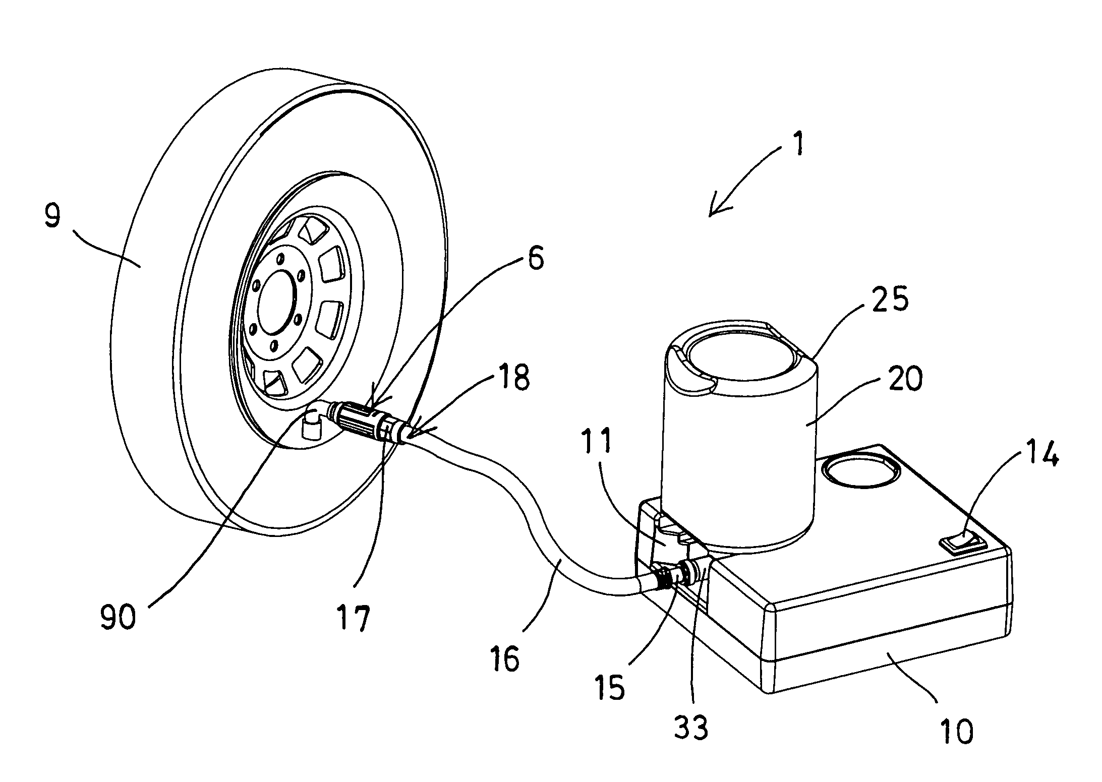
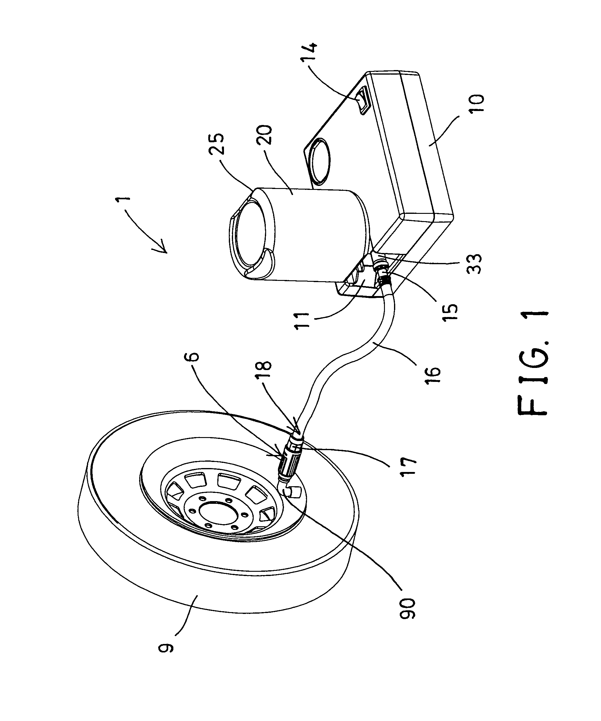
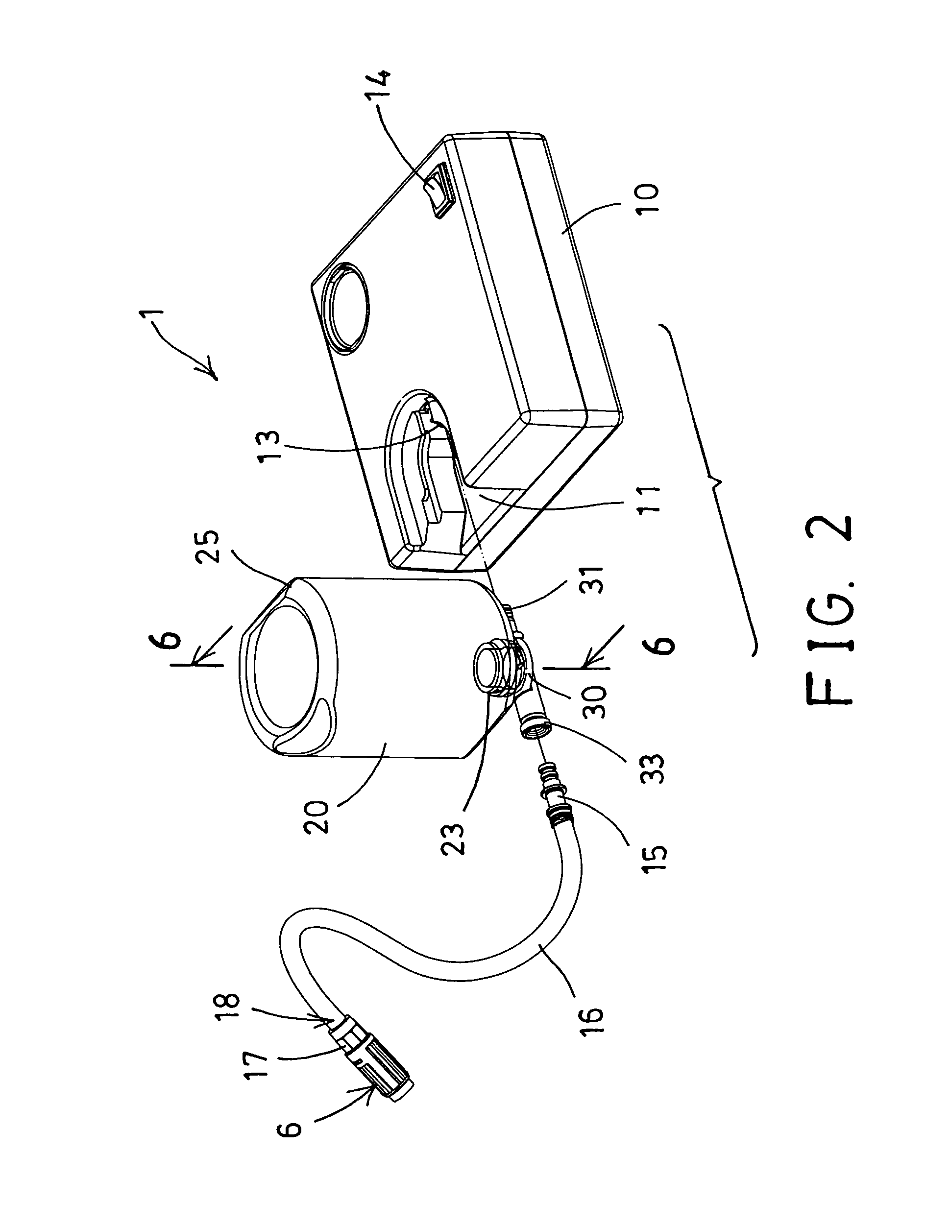
[0042]Referring to the drawings, and initially to FIGS. 1-3, a sealing and inflating assembly 1 in accordance with the present invention comprises a receptacle 10 including a socket opening 11 formed therein, an air compressing device 12 disposed or received or engaged into the receptacle 10 and including an outlet tube 13 extended outwardly therefrom and partially extended into the socket opening 11 of the receptacle 10, and a control switch 14 electrically connected or coupled to the air compressing device 12 for controlling or operating the air compressing device 12 to selectively generate a pressurized air of a relatively greater air pressure and a decreased flowing quantity. The above-described structure is typical and will not be described in further details.

[0043]Several examples of the typical air compressing devices or sealing and inflating devices are disclosed in the cited prior U.S. patents which may be taken as the references for the present invention. For example, the ...


PUM

PropertyMeasurementUnit
heightaaaaaaaaaa
swellingaaaaaaaaaa
inner diameteraaaaaaaaaa

Abstract

A sealing and inflating assembly includes an air compressor device engaged in a receptacle for generating a pressurized air, and a tire repairing container for receiving a sealing preparation, an outlet piece attached to a mouth opening of the tire repairing container and having an inlet conduit and an outlet conduit, a pipe is disposed in the container and includes one end coupled to the outlet piece and includes a bore for directing the pressurized air to flow through the bore of the pipe and to flow into a base portion of the container without flowing through the sealing preparation, for allowing the tire sealing preparation to be effectively supplied to seal and inflate the inflatable objects.

Description

BACKGROUND OF THE INVENTION[0001]1. Field of the Invention[0002]The present invention relates to an air compressor or a sealing and inflating assembly for sealing and inflating an inflatable object, and more particularly to an air compressing device including an improved tire repairing container for quickly coupling and attaching and securing to an outlet tube of the air compressor and for quickly disengaging from the air compressor and for allowing the tire sealing preparation to be effectively supplied to seal and inflate the inflatable objects.[0003]2. Description of the Prior Art[0004]Various kinds of typical air compressing devices have been developed by the applicant and comprise a cylinder housing, a piston slidably received in the cylinder housing, and a motor coupled or attached to the cylinder housing and coupled to the piston for moving the piston relative to the cylinder housing in a reciprocating action, in order to generate a pressurized air of a greater air pressure a...

Claims


Application Information

Patent Timeline
Patent Type & Authority Patents(United States)
IPC IPC(8): B29C73/02B65B31/00
CPCB29C73/166B29L2030/00B60S5/046B60S5/04
Inventor CHOU, WEN, SAN
Owner CHOU WEN SAN
Why Eureka
Try Eureka