Electrical power supply and control device for equipment of a rotor, and an aircraft fitted with such a device

a technology of electric power supply and control device, which is applied in the direction of propellers, propulsive elements, water-acting propulsive elements, etc., can solve the problems of reducing the number of passengers, duplicate units, and heavy weight of the first device combining an electrical unit with slip rings

Active Publication Date: 2014-01-14
EUROCOPTER
View PDF15 Cites 15 Cited by
  • Summary
  • Abstract
  • Description
  • Claims
  • Application Information

AI Technical Summary

Benefits of technology

[0022]An object of the present invention is thus to propose a relatively lightweight device that makes it possible to overcome the above-mentioned limitations, without disturbing equipment arranged in the airframe and not requiring large amounts of maintenance.
[0032]As explained below, the contactless connection means may serve to transfer any type of information both from the airframe to the rotor and from the rotor to the airframe, without degrading performance.
[0034]As a result, the novel combination of the device provides for multiple elements that operate in synergy to provide an alternative that is advantageous compared with known devices.

Problems solved by technology

Furthermore, for safety reasons, the electrical unit is duplicated.
That first device combining an electrical unit with slip rings is very heavy, in particular because of the large number of electric cables and slip rings.
However installing such a device on a medium weight rotorcraft may reduce the number of passengers by two, for example.
Furthermore, the friction between each brush and the corresponding slip ring tends to degrade the performance of the slip rings.
Unfortunately, the slip rings are sometimes difficult to access, and the cost of maintenance may be high, requiring the rotorcraft to be grounded for a long time.
Finally, it should be observed that since the electrical unit is installed in the airframe of the aircraft, the electrical unit is likely to disturb nearby electrical equipment.
Furthermore, the electrical unit presents non-negligible bulk and is therefore penalizing.
Nevertheless, the data transmission rate and the observed interference limit that technology to restricted applications.
It is difficult to cause a low power signal coming from a temperature or ice sensor, for example, to transit via slip rings or a carrier current.

Method used


Image

  • Electrical power supply and control device for equipment of a rotor, and an aircraft fitted with such a device
  • Electrical power supply and control device for equipment of a rotor, and an aircraft fitted with such a device
  • Electrical power supply and control device for equipment of a rotor, and an aircraft fitted with such a device

Examples


Embodiment Construction

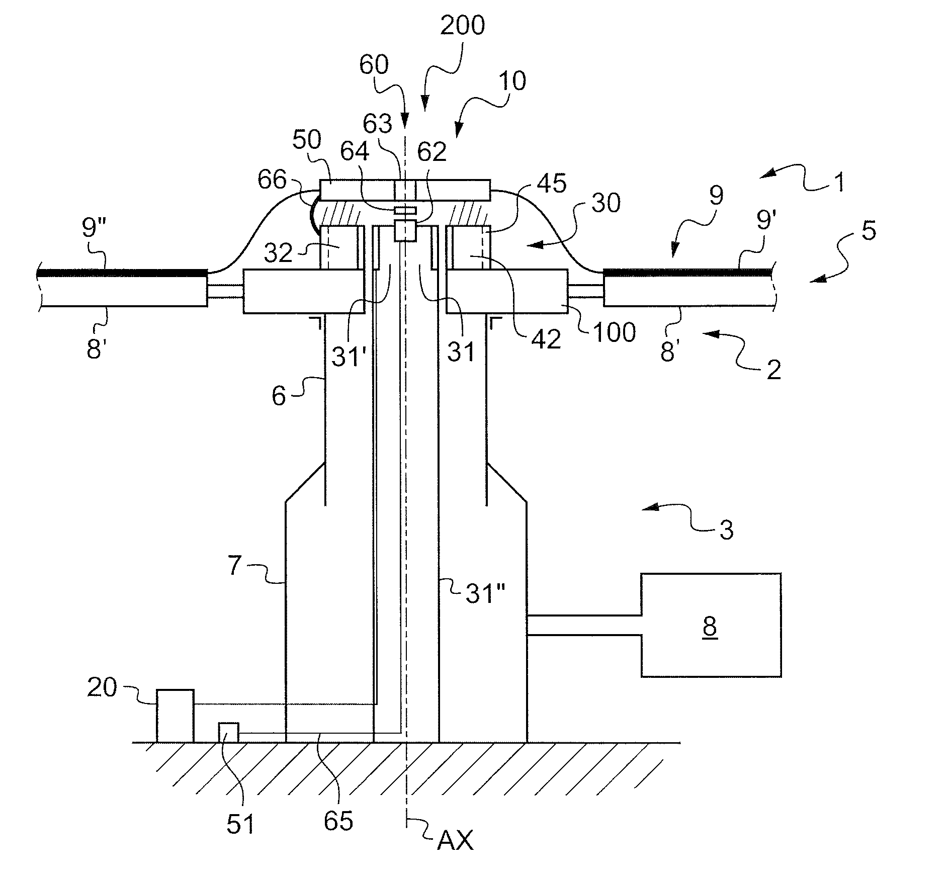
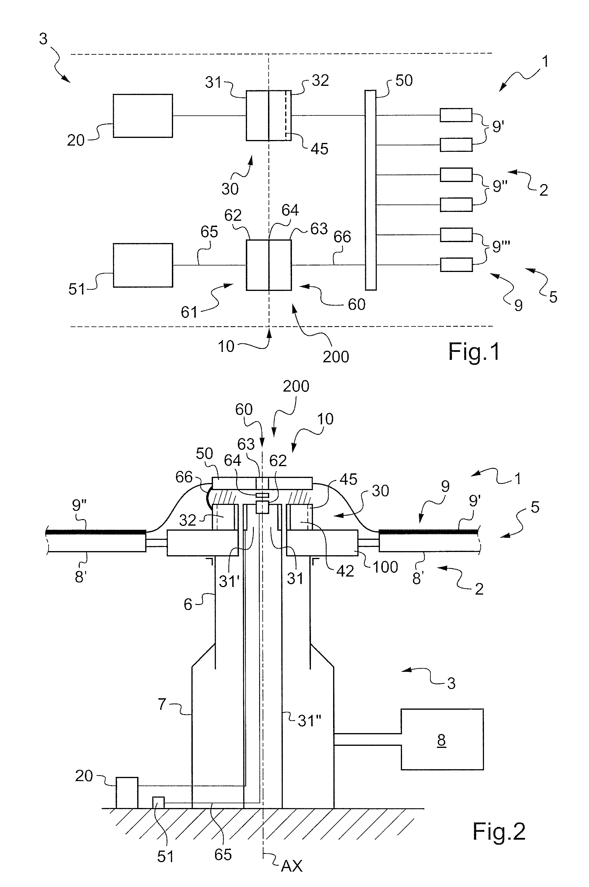
[0067]FIG. 1 shows an aircraft 1 of the invention in diagrammatic manner.

[0068]The aircraft 1 comprises an airframe 3 and a rotor 5, e.g. an antitorque rotor or a rotor of a rotary wing 2 of a rotorcraft, or indeed a propeller of an aircraft.

[0069]A stationary frame of reference is associated with the airframe 3, while conversely a rotary frame of reference is associated with the rotor 5, the rotary frame of reference rotating about the axis of rotation of the rotor 5 relative to the stationary frame of reference.

[0070]The stationary elements of the airframe 3 are then said to be “stationary”, whereas in contrast the elements that are rotating together with the rotor 5 relative to the airframe 3 are said to be “rotary”.

[0071]The invention provides a device 10 for electrically powering and controlling equipment 9 fastened to the rotor 5. By way of example, for a rotor having three blades, the equipment 9 may comprise first heater mats 9′ for a first blade, second heater mats 9″ for a...


PUM


Abstract

The present invention relates to an electrical power supply and control device (10) for equipment (9) of a rotor (5), the device having a three-phase AC generator (20) in a stationary frame of reference. The device (10) comprises a rotary field transformer (30) having a stationary portion (31) connected to said generator (20) and a rotary portion (32) connected to a sequencer (50) that is arranged in a rotary frame of reference, said device (10) including control means (51) for controlling the sequencer (50) and located in said stationary frame of reference, the control means being connected to the sequencer (50) via contactless connection means (200), said sequencer (50) being suitable for electrically powering said equipment (9) on order of said control means (51).

Description

CROSS REFERENCE TO RELATED APPLICATIONS[0001]This application claims the benefit of FR 10 02257 filed on May 28, 2010, the disclosure of which is incorporated in its entirety by reference herein.BACKGROUND OF THE INVENTION[0002](1) Field of the Invention[0003]The present invention relates to an electrical power supply and control device for equipment of a rotor, and to an aircraft fitted with such a device.[0004]The invention thus lies in the technical field of electrical power supply and control means for equipment present on a rotary rotor, with passage from a stationary frame of reference to a rotary frame of reference. More particularly, the technical field is that of electrical power supply and control means for de-icing and anti-icing means of a rotorcraft rotor.[0005](2) Description of Related Art[0006]A first device is known that has an alternating current (AC) generator connected to an electrical unit sometimes referred to as a “power de-icing” unit. The electrical unit is ...

Claims


Application Information

Patent Timeline
Patent Type & Authority Patents(United States)
IPC IPC(8): B64D15/12
CPCB64D15/14B64C27/04B64D15/12H02J4/00B64C27/32
Inventor IMBERT, NICOLASCHUC, CHARLES
Owner EUROCOPTER
Why Eureka
Try Eureka