
Window regulator assembly for a vehicle

a technology for window regulators and vehicles, applied in the direction of winding mechanisms, hoisting equipment, doors, etc., can solve the problems of the configuration of the lifter plate assemblies themselves, the force required to insert a window into the lifter plate assembly is relatively high, and the joint between the pulleys and the carrier may be subject to premature failur

Active Publication Date: 2014-01-21
MAGNA CLOSURES INC
View PDF29 Cites 8 Cited by
  • Summary
  • Abstract
  • Description
  • Claims
  • Application Information

AI Technical Summary

Benefits of technology

The solution reduces the likelihood of binding and premature failure, lowers the cost by using less expensive motor components, enhances window retention, and stabilizes the door handle during transport and installation.

Problems solved by technology

There are several problems, however, with these window regulator assemblies.
Due to the forces involved in moving the window, however, the joint between the pulleys and the carrier may be subject to premature failure.
Another problem resides in the configuration of the lifter plate assemblies themselves.
However, the force required to insert a window into the lifter plate assembly is relatively high.
Another problem is that the window regulator lifter plate assemblies are prone to binding or sticking as they move along the rails.
However, the large motors increase the overall cost of the window regulator assemblies.
Another problem is that, when a door handle assembly is mounted to the carrier, the door handle itself can swing during transport or during installation of the carrier in a door assembly, which can cause the door handle to catch on something, potentially causing damage.

Method used


Image

  • Window regulator assembly for a vehicle
  • Window regulator assembly for a vehicle
  • Window regulator assembly for a vehicle

Examples


Embodiment Construction

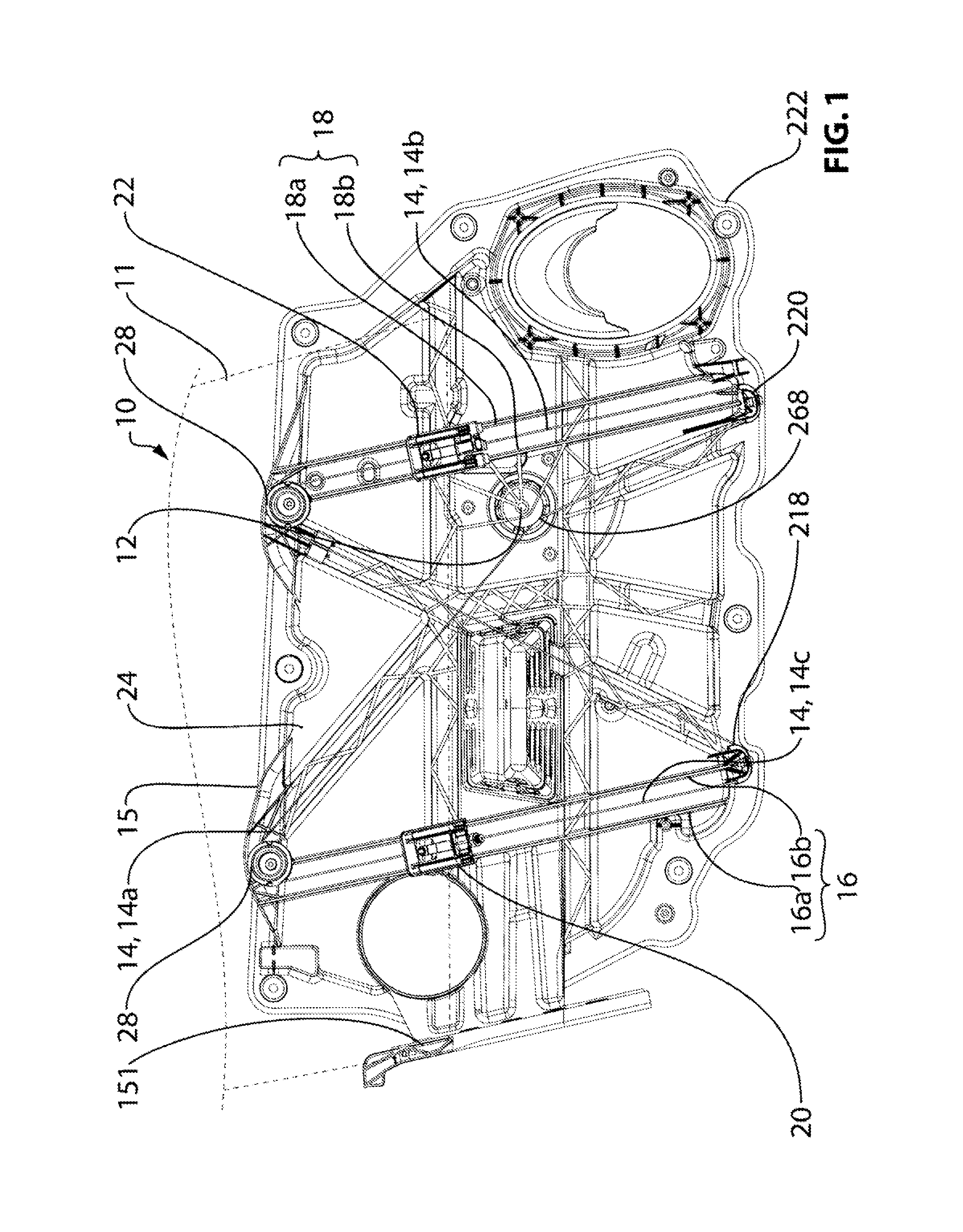
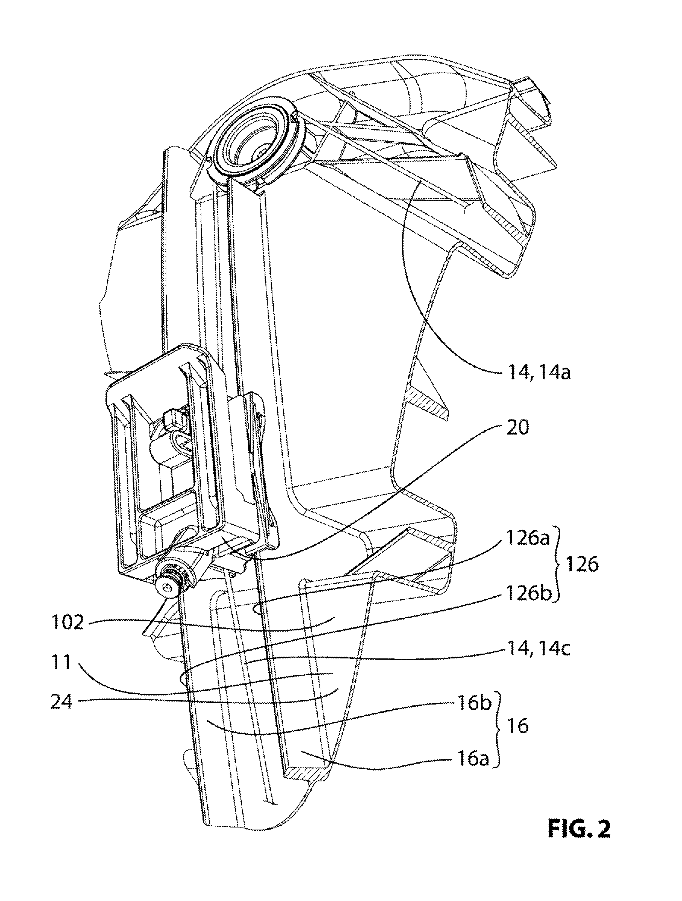
[0077]Reference is made to FIG. 1, which shows a window regulator assembly 10 for moving a vehicle window 11 up and down in accordance with an embodiment of the present invention. The window regulator assembly 10 includes a drive motor 12, a set of drive cables 14, including a first drive cable 14a, a second drive cable 14b and a third drive cable 14c, a carrier 15, which includes a first set of rails 16 and second set of rails 18, a first lifter plate 20 and a second lifter plate 22.

[0078]The drive motor 12 drives vertical movement of the first and second lifter plates 20 and 22 on the set of rails 16 and 18 respectively by means of the drive cables 14.

[0079]The carrier 15 is itself mountable to the interior of a door assembly (not shown) that forms part of a vehicle. In the embodiment shown in FIG. 1, the carrier 15 is a structural element, and is configured to withstand loads incurred during operation of window regulator assembly 10. The carrier 15 includes a carrier body 24 and ...


PUM


Abstract

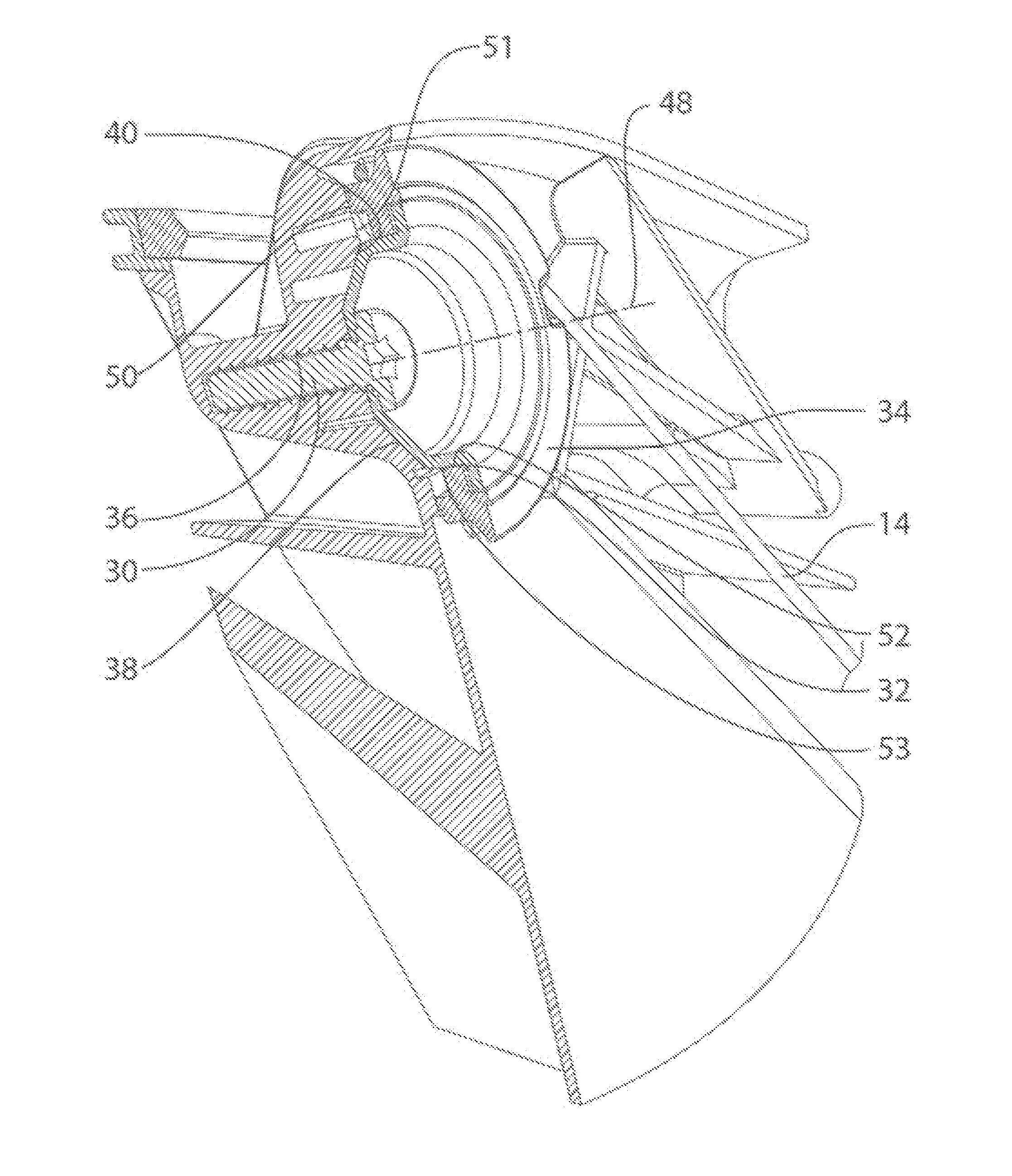
In an aspect, the invention is directed to a combination of a carrier and a pulley assembly. The pulley assembly includes a pulley having an associated pulley rotation axis, a pulley bearing member and a pulley fastener. The pulley fastener connects the pulley assembly to the carrier. The pulley bearing member includes a pulley assembly bending load bearing surface. The carrier is mountable to a vehicle and includes a pulley fastener mount for receiving the pulley fastener. The carrier further includes a carrier bending load bearing surface that engages the pulley bending load bearing surface. The pulley assembly bending load bearing surface is generally conical about the pulley rotation axis and tapers outwardly in a direction axially towards the pulley. The carrier bending load bearing surface is generally inner-conical about the pulley rotation axis.

Description

CROSS-REFERENCE TO RELATED APPLICATIONS[0001]This application is a national phase entry filed under 35 U.S.C. section 371, of PCT application no. PCT / CA08 / 000,892 filed May 9, 2008, which claims priority to U.S. Provisional No. 60 / 916,860 filed May 9, 2007 and U.S. Provisional No. 60 / 968,364 filed Aug. 28, 2007.FIELD OF THE INVENTION[0002]The present invention relates to window regulator assemblies for vehicles.BACKGROUND OF THE INVENTION[0003]Vehicle doors typically have windows that can be opened and closed. Within the door, there is typically a window regulator assembly including a carrier, a motor, first and second rails and two window regulator lifter plate assemblies which are driven along the rails by the motor.[0004]There are several problems, however, with these window regulator assemblies. For example, in situations where the window regulator lifter plate assemblies are driven by cables connected to the motor, there are pulleys that are used to effect a change in direction...

Claims


Application Information

Patent Timeline
Patent Type & Authority Patents(United States)
IPC IPC(8): E05F11/48
CPCE05F11/382E05Y2600/00E05F2011/387E05F11/485E05F11/385B60J5/0416E05Y2900/55E05Y2800/692E05Y2600/13E05Y2800/26E05Y2201/668E05Y2201/224E05Y2800/29E05Y2201/654E05Y2201/612F16H55/50E05Y2201/684E05Y2201/47E05F11/483B60J5/0402B60J1/007B60J1/17B60J5/0408B60J5/06E05F11/488E05F15/086E05F15/689E05Y2600/53E05Y2900/50E05Y2201/706
Inventor BROADHEAD, DOUGLAS G.FORTIN, RAYMOND EDWARDMIU, TRAIANMELLARY, THOMASFERRI, JAMES J.SMITH, DONALD HARRY
Owner MAGNA CLOSURES INC
Learn More