Glare management of reflective and thermoreflective surfaces

a technology of reflective surfaces and thermoreflective surfaces, applied in the direction of instruments, polarising elements, other domestic objects, etc., can solve the problems of limited switching speed and cycle lifetime, reduced visibility, and solar heat gain, and achieve the effect of reducing the effect of glar

Inactive Publication Date: 2014-01-21
RAVENBRICK
View PDF256 Cites 9 Cited by
  • Summary
  • Abstract
  • Description
  • Claims
  • Application Information

AI Technical Summary

Benefits of technology

[0018]Variable, selective, or asymmetric diffusive optics may be used to mitigate the effects of glare from reflective or thermoreflective surfaces. This technology has particular, but not exclusive, application as a glare reduction method for building surfaces.
[0020]In one implementation, a method is provided for reducing glare from partially reflective or thermoreflective surfaces without significantly degrading the energy benefits of reflection. The method involves placing an at least partially diffusive filter between either a partially reflective surface or a thermoreflective surface and an external light source. When light is transmitted through the partially reflective surface or the thermoreflective surface, it is diffused only once. However, when light is reflected from the partially reflective surface or the thermoreflective surface, it is diffused twice, thereby transforming specular reflections from the partially reflective surface or the thermoreflective surface into diffusive reflections.
[0022]In a further implementation an energy-efficient device is disclosed that reduces glare from reflection of incident radiant energy. The device may be composed of a first diffusively reflective polarizer, a second diffusively reflective polarizer, a depolarizer positioned between the first diffusively reflective polarizer and the second polarizer, and a transparent substrate affixed to the second diffusively reflective polarizer.
[0023]In yet another implementation, an energy-efficient device is described that reduces glare from reflection of incident radiant energy. The device may be composed of a first diffusively reflective polarizer, a second diffusively reflective polarizer, a depolarizer positioned between the first diffusively reflective polarizer and the second polarizer, and a transparent substrate affixed to the second diffusively reflective polarizer
[0030]Use of diffusive optical sheets or films as described herein may allow builders, architects, building owners, and vehicle designers to reap the energy benefits of reflective and thermoreflective materials, while minimizing external and / or internal glare from building or vehicle surfaces. It may also provide an aesthetic alternative to mirror finishes for building and vehicle exteriors with little or no harm to energy efficiency and may further reduce reflective window glare for inside and / or outside observers while permitting a clear view of the outside for building or vehicle occupants. Such diffusive optics may provide privacy for building and vehicle interiors, similar to diffusive “privacy glass” but with significantly less effect on the view from inside.
[0031]This technology may use both specular and diffusive technologies to create windows for transparent and privacy type models of windows, and prevent the concentration of reflected solar energy in UV, visible, or IR bands in different ways. This technology may also be used to reflect or transmit, diffusively or specularly, various polarizations and frequency ranges of light in different ways at different temperatures to reduce glare.

Problems solved by technology

The design, composition, and benefits of reflective coatings are well documented and need no further elaboration here, except to note that the reduction in solar heat gain, while clearly beneficial in hot, sunny conditions, may be detrimental in cold weather as it interferes with passive solar heating.
These switchable mirrors, which are analogous to rechargeable batteries, may rely on the physical migration of ions across a barrier under the influence of an electric field and, therefore, have limited switching speeds and cycle lifetimes. In addition, electrically operated “light valves” that combine liquid crystals with one or more reflective polarizers are described, for example, in U.S. Pat. No. 6,486,997 to Bruzzone et al.
Any surface which presents a mirror finish in the presence of a light source, whether indoors or outdoors, has the potential to create glare, i.e., a condition in which background illumination approaches, equals, or exceeds the illumination of objects in the foreground, which in some case can lead to discomfort or reduced visibility.
For this reason, mirrored films are banned or discouraged in some jurisdictions and are the subject of increased scrutiny in others.
Instead, reflection is achieved by photon interaction with conduction electrons (e.g., in a metal) or by constructive and destructive interference between layers of different material (e.g., in a dielectric mirror).
However, a diffusive coating will cause the reflected light to be scattered, producing a white surface which may still be highly reflective, but not specular (i.e., mirror-like) and therefore not capable of reflecting or transmitting an intelligible, collimated image.
However, these are not true one-way devices.

Method used


Image

  • Glare management of reflective and thermoreflective surfaces
  • Glare management of reflective and thermoreflective surfaces
  • Glare management of reflective and thermoreflective surfaces

Examples


Embodiment Construction

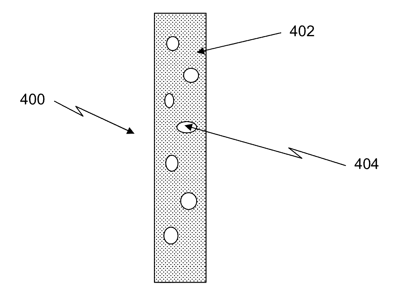
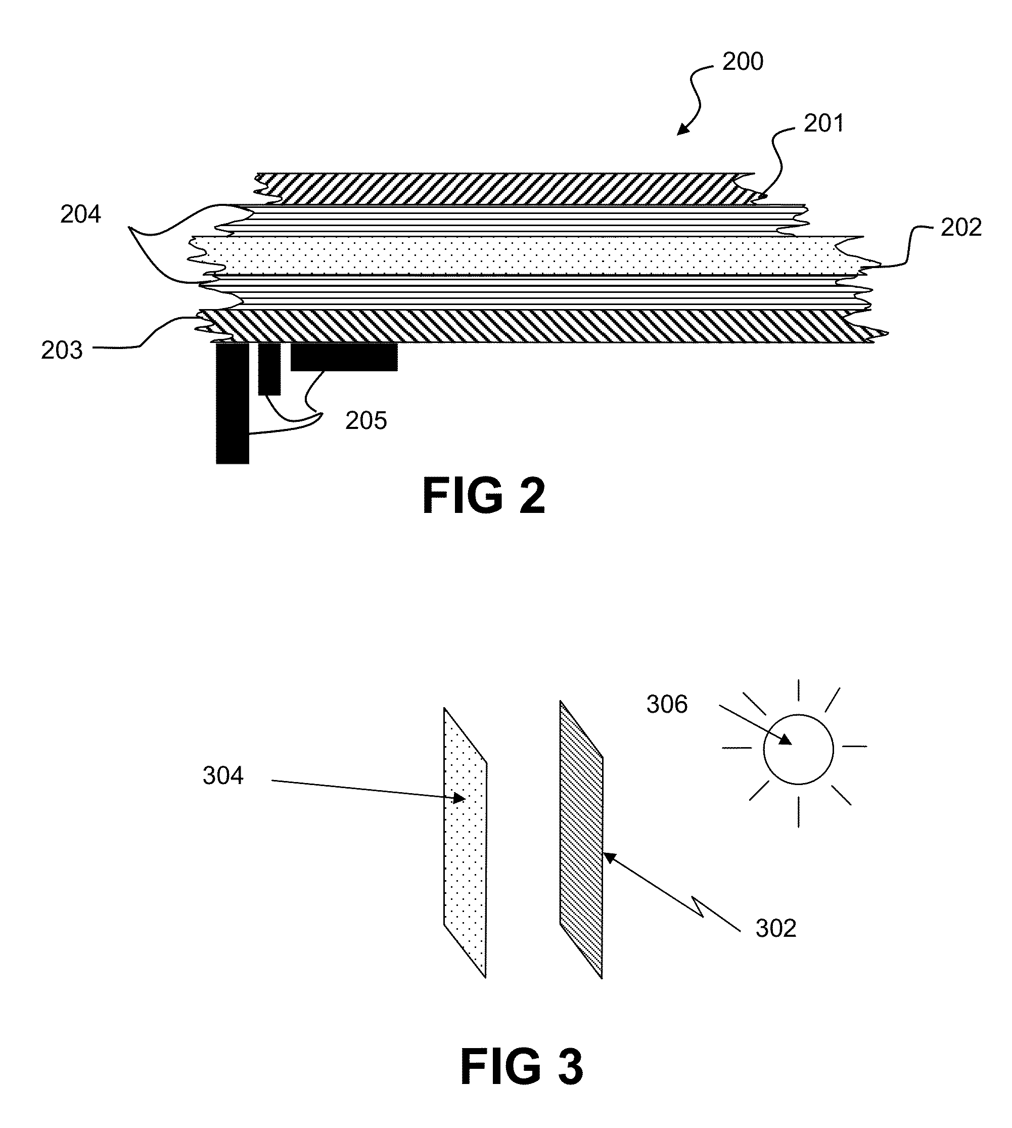
[0047]Variable, selective, or asymmetric diffusive optics may be used to reduce specular reflection from mirrored surfaces, including reflective and thermoreflective building materials. For the purposes of this specification, the term “thermoreflective” shall refer to any object, device, or material having a reflectivity that varies as a function of temperature. Since glare is primarily a function of specular rather than diffusive reflection of a bright light source, this technology may reduce glare from building, vehicle, and other surfaces.

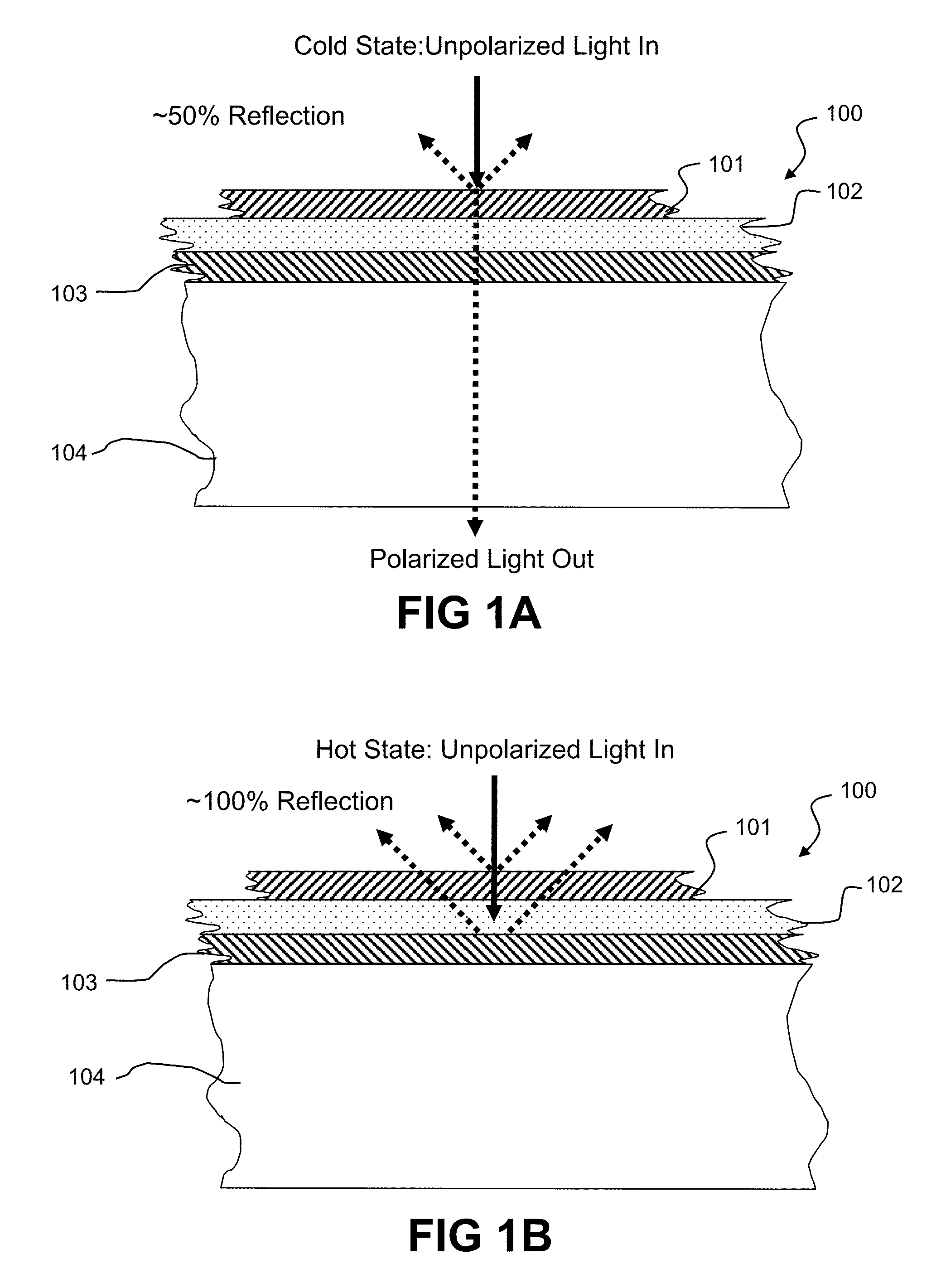
[0048]U.S. patent application Ser. No. 12 / 019,602 to McCarthy et. al. discloses “thermoreflective” window filters that are largely transparent when cold and largely reflective when hot, and which may be used to regulate the temperatures of buildings when incorporated into windows. One possible embodiment based upon the disclosure is a passive temperature-regulating film for use as a construction material, which may comprise an appliqué that can ...


PUM

PropertyMeasurementUnit
specular reflectivityaaaaaaaaaa
reflectivityaaaaaaaaaa
energy-efficientaaaaaaaaaa

Abstract

The reflectivity and transmissivity of building and vehicle surfaces is maintained while employing partial, variable, selective, or asymmetric diffusers between a surface and an external light source such that the reflected light is diffused to produce a reduction in glare, while minimally effecting the specular or collimated transmission (if any) of light through the surface. Glare is also reduced by utilizing diffuser devices that reflect light in a temperature dependent manner.

Description

CROSS REFERENCE TO RELATED APPLICATIONS[0001]This application claims priority pursuant to 35 U.S.C. §119(e) to the following: U.S. provisional patent application No. 61 / 047,400 entitled “Glare management method for reflective and thermoreflective surfaces” filed 23 Apr. 2008; U.S. provisional patent application No. 61 / 083,138 entitled “Glare management method for reflective and thermoreflective surfaces” filed 23 Jul. 2008; U.S. provisional patent application No. 61 / 084,940 entitled “Glare management method for reflective and thermoreflective surfaces” filed 30 Jul. 2008; U.S. provisional patent application No. 61 / 146,207 entitled “Glare management method for reflective and thermoreflective surfaces” filed 21 Jan. 2009; and U.S. provisional patent application No. 61 / 157,076 entitled “Glare management method for reflective and thermoreflective surfaces” filed 3 Mar. 2009, the disclosures of which are hereby incorporated herein by reference in their entirety.[0002]This application is ...

Claims


Application Information

Patent Timeline
Patent Type & Authority Patents(United States)
IPC IPC(8): G02B5/30G02F1/19
CPCG02F2201/346G02B5/0242G02B5/0284G02B5/0247G02B5/0268G02F2201/38G02F2001/133548G02B5/0252G02B27/281G02B5/0289G02B5/3058G02F2001/133545G02B5/0294G02B5/0278G02B5/0231B32B37/18B32B38/1808B32B2307/42B32B2551/00G02F1/0147G02F1/133545G02F1/133548
Inventor POWERS, RICHARD M.MCCARTHY, WIL
Owner RAVENBRICK
Why Eureka
Try Eureka