
Mold for producing simulated blood vessel, method of producing simulated blood vessel and simulated blood vessel

a technology of simulated blood vessels and molds, which is applied in the direction of stereotype printing, educational models, instruments, etc., can solve the problems of extreme difficulty in creating an animal with such a lesioned blood vessel with a high degree of reproducibility, and achieves the effects of low cost, high strength, and stable formation

Active Publication Date: 2014-01-28
WASEDA UNIV
View PDF17 Cites 44 Cited by
  • Summary
  • Abstract
  • Description
  • Claims
  • Application Information

AI Technical Summary

Benefits of technology

The patent describes a new technology that helps improve the accuracy and reliability of infrared temperature measurement. This technology involves using a special coating on the surface of an infrared thermometer to prevent stray electrical signals from interfering with the temperature measurement. By doing this, the technology makes it easier to get accurate readings from the infrared thermometer, even when the thermometer is used in difficult conditions.

Problems solved by technology

However, there is no technique for creating any lesioned animal whose blood vessel is narrowed through calcification, and if such a technique exist, it may be extremely difficult to create an animal having such a lesioned blood vessel with a high degree of reproducibility.

Method used


Image

  • Mold for producing simulated blood vessel, method of producing simulated blood vessel and simulated blood vessel
  • Mold for producing simulated blood vessel, method of producing simulated blood vessel and simulated blood vessel
  • Mold for producing simulated blood vessel, method of producing simulated blood vessel and simulated blood vessel

Examples


Embodiment Construction

[0030]Hereinafter, an embodiment of the present invention will be described with reference to the accompanying drawings.

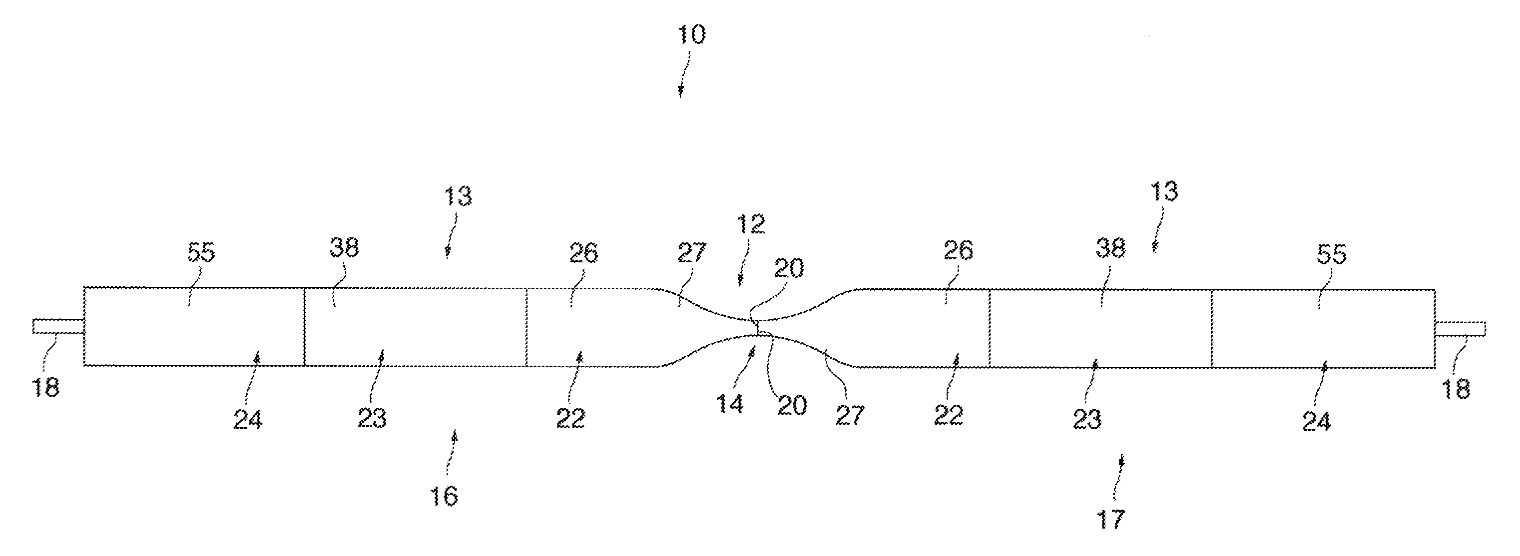
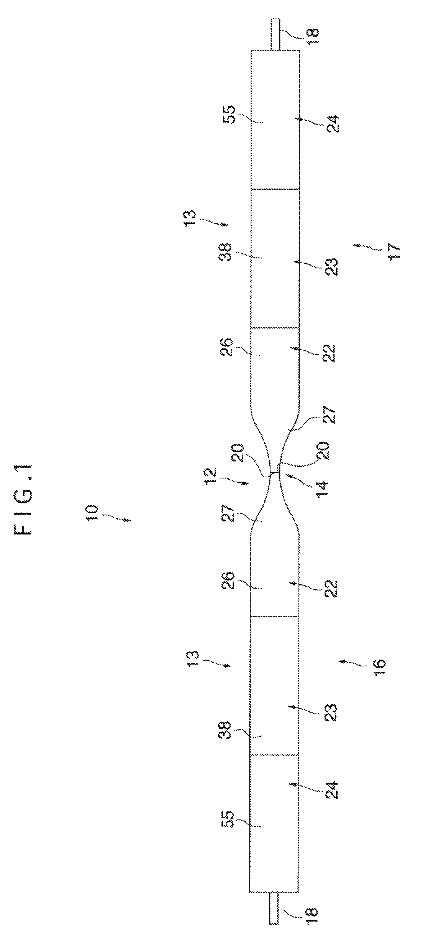
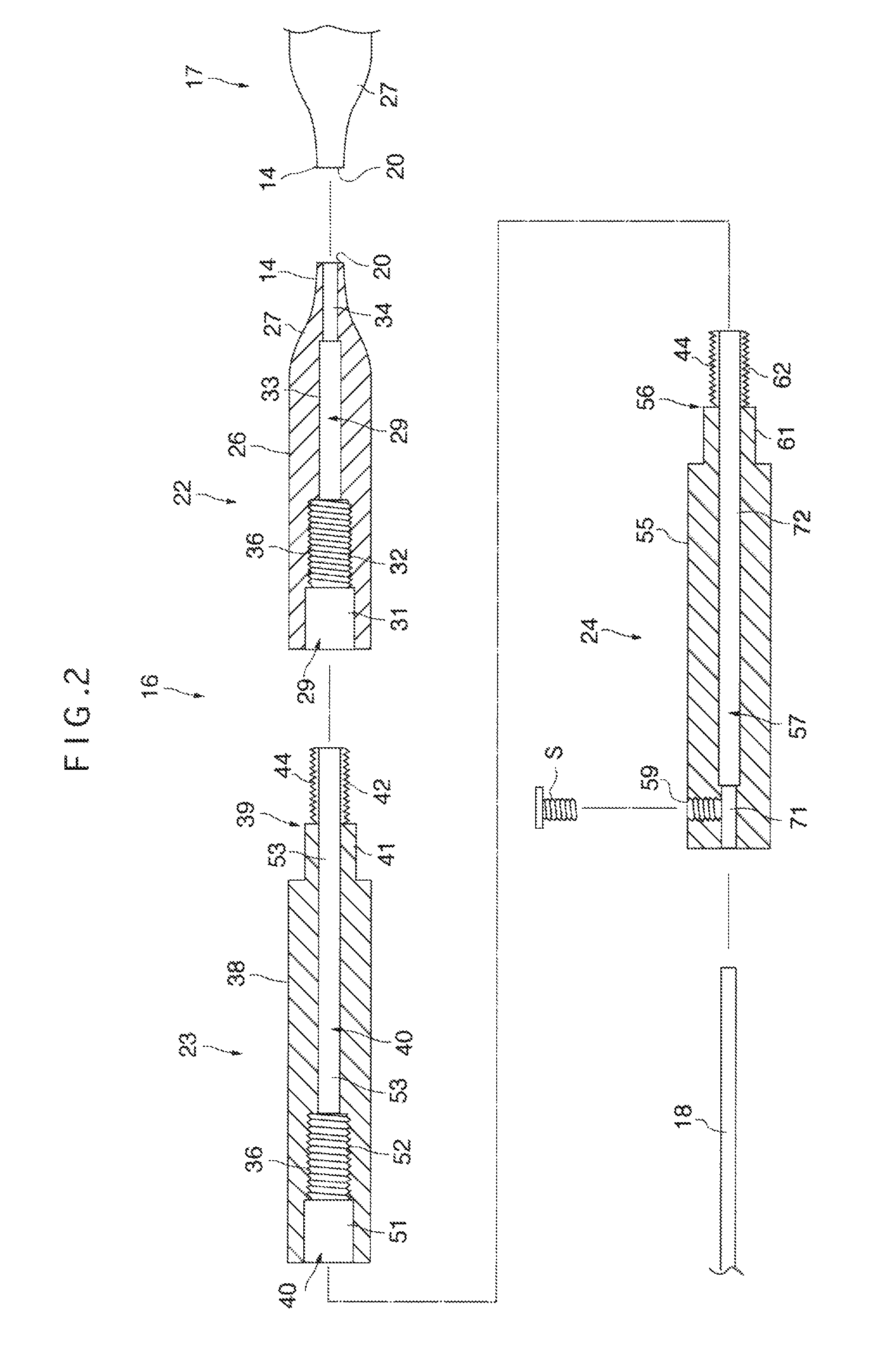
[0031]FIG. 1 shows a schematic plan view of a mold according to the present embodiment. In this figure, a mold 10 is shaped like a round bar made of stainless steel with a concave 12 formed substantially in the center in the left-to-right direction and is made divisible in an axial direction at a center part 14 substantially in the center in the left-to-right direction of the concave 12. The mold 10 is configured by including a first molded member 16 located on the left side of the center part 14 in the FIG. 1, a second molded member 17 located on the right side of the center part 14 in the figure and a round bar-shaped axial member 18 that penetrates the interior of the first and second molded members 16 and 17.

[0032]The first and second molded members 16 and 17 have substantially the same shape, are arranged to be symmetric to each other in an operating condition...


PUM

PropertyMeasurementUnit
diameteraaaaaaaaaa
hardnessaaaaaaaaaa
concentrationaaaaaaaaaa

Abstract

Disclosed is a method whereby a narrowed part similar to an actual lesioned blood vessel can be easily obtained. A mold (10) comprises first and second molded members (16, 17) having inner spaces (29, 40, 57) passing through in the axial direction and an axial member (18) detachably inserted through the individual inner spaces (29, 40, 57) of the individual molded members (16, 17). The molded members (16, 17) have tapered front parts (27, 27) respectively. In the state of facing the front ends (20) of the tapered front parts (27) to each other and thus forming a concave (12), the axial member (18) is attached. A first material (75) made of a mixed material comprising calcium carbonate or the like and silicone or the like is applied to the concave (12). A second material (76) such as silicone is applied to the entire outer periphery of the mold (10). After hardening the materials (75, 76), the mold (10) is withdrawn by detaching the axial member (18) and dividing the concave (12). Thus, a simulated blood vessel (78) having a simulated narrowed part of the blood vessel caused by calcification can be obtained.

Description

TECHNICAL FIELD[0001]The present invention relates to a mold for producing a simulated blood vessel, a method of producing a simulated blood vessel and a simulated blood vessel, and more particularly, to a simulated blood vessel and a method of producing a simulated blood vessel and a mold used for producing a simulated blood vessel suitable for a performance test of a stent, training of cardiac surgery such as coronary artery bypass surgery and manipulation evaluation.BACKGROUND ART[0002]When a blood vessel is narrowed through plaque formation whereby fat is deposited or calcification or the like, the lumen of the blood vessel is expanded using a medical instrument called “stent” to secure blood circulation. For this stent, as other medical instruments, it is extremely important to evaluate the validity and safety thereof through an animal experiment or using an extracorporeal apparatus simulating a patient's lesion before applying it to the patient. However, there is no technique ...

Claims


Application Information

Patent Timeline
Patent Type & Authority Patents(United States)
IPC IPC(8): G09B23/28
CPCG09B23/30G09B23/288
Inventor IWASAKI, KIYOTAKAUMEZU, MITSUOTANAKA, TAKASHI
Owner WASEDA UNIV
Learn More