Shock wave electrodes

a technology of shock wave and electrode, applied in the field of shock wave electrode, can solve the problems of high voltage applied across the inner wire and the outer cable, and achieve the effect of propagating away from the exposed tips

Active Publication Date: 2017-05-18
SHOCKWAVE MEDICAL
View PDF13 Cites 47 Cited by
  • Summary
  • Abstract
  • Description
  • Claims
  • Application Information

AI Technical Summary

Benefits of technology

[0008]Any of the electrode pairs described herein may comprise a first electrode having a recess and a second electrode adjacent to and co-planar with the first electrode and having a protrusion and the recess may have a concave curve and the protrusion may have a convex curve that corresponds with the concave curve. An electrode may comprise a proximal end, a distal end, and a spiral body therebetween. The spiral body may comprise one or more helices that wrap along the outer surface of the elongate body.
[0009]Another variation of a shock wave catheter may comprise an axially extending elongate member, a first electrode circumferentially disposed over an outer surface of the elongate member, the first electrode comprising a first electrically conductive region having a first surface area and a second electrode circumferentially disposed over the outer surface of the elongate member that is coplanar and adjacent to the first electrode. The second electrode may comprise a second electrically conductive region having a second surface area that is greater than the first surface area. A spark gap may be formed by a separation between the conductive region of the first electrode and the conductive region of the second electrode such that when a voltage is applied across the first and second electrodes, a current may flow across the spark gap between the first electrode and the second electrode such that a shockwave is initiated at the spark gap. Some variations may further comprise a voltage source, and a first wire may connect the first electrode to a positive terminal of the voltage source, and a second wire may connect the second electrode to a negative terminal of the voltage source, and the first wire and the second wire may be located on the outer surface of the elongate member. The axially extending elongate member may comprise a guide wire lumen extending therethrough. In some variations, the conductive region of the first electrode may have a first arcuate portion and the conductive region of the second electrode may have a second arcuate portion that is complementary to the first arcuate portion. For example, the first arcuate portion may comprise a convex curve and the second arcuate portion may comprise a concave curve. Alternatively or additionally, the first arcuate portion may comprise a concave curve and the second arcuate portion may comprise a convex curve. The radius of curvature of the first arcuate portion may be larger than the radius of curvature of the second arcuate portion, or alternatively, the radius of curvature of the first arcuate portion may be less than the radius of curvature of the second arcuate portion. The first arcuate portion may comprise a circular protrusion and the second arcuate portion may comprise a circular groove. Alternatively, the first arcuate portion may comprise a circular groove and the second arcuate portion may comprise a circular protrusion. A ratio of the surface area of the first conductive region to the surface area of the second conductive region may be from about 1:2 to about 1:20, e.g., from about 1:4 to about 1:10. The second electrode may comprise a proximal end, a distal end, and an electrically conductive body extending therebetween. The electrically conductive body may comprise one or more flexible spirals and / or one or more flexible helices. The electrically conductive body may comprise a flexible twisted portion.
[0010]Other variations of a shock wave catheter may comprise an axially extending elongate member, a first ring electrode mounted circumferentially around the elongate member, a second ring electrode mounted circumferentially around the elongate member and positioned adjacent to the first ring electrode, and a third ring electrode mounted circumferentially around the elongate member and positioned adjacent to the first ring electrode. A first spark gap may be defined between the first and second ring electrodes and a second spark gap may be defined between the second and third ring electrodes. Each spark gap may include an arcuate recess formed along a side edge of one of the ring electrodes and a complimentary arcuate projection formed along the side edge of the adjacent ring electrode, where the projection may fit into the associated recess. The first spark gap may be circumferentially offset from the second spark gap. The first and third ring electrodes may be connectable to a high voltage source. The second ring electrode may be a non-insulated metal and the recess of the first and second spark gaps may be formed in the second ring electrode. The projection of the first spark gap may be formed in the first ring electrode and the projection of the second spark gap may be formed in the third ring electrode, where the first and second ring electrodes may have an insulating coating except in the region of the projections. The surface area of the second ring electrode may be greater than the surface area of each of the projections of the first and third ring electrodes. The first electrode and the third electrode may each have a proximal portion, a distal portion, and a body therebetween, where the body may extend longitudinally along the axially extending elongate member and may comprise a spiral. In some variations, the body may comprise a helix, and / or one or more turns around the surface of the elongate member.

Problems solved by technology

In this arrangement, a high voltage applied across the inner wire and outer cable gives rise to a shock wave that propagates away from the exposed tips of the inner wire and outer cable.

Method used


Image

  • Shock wave electrodes
  • Shock wave electrodes
  • Shock wave electrodes

Examples


Embodiment Construction

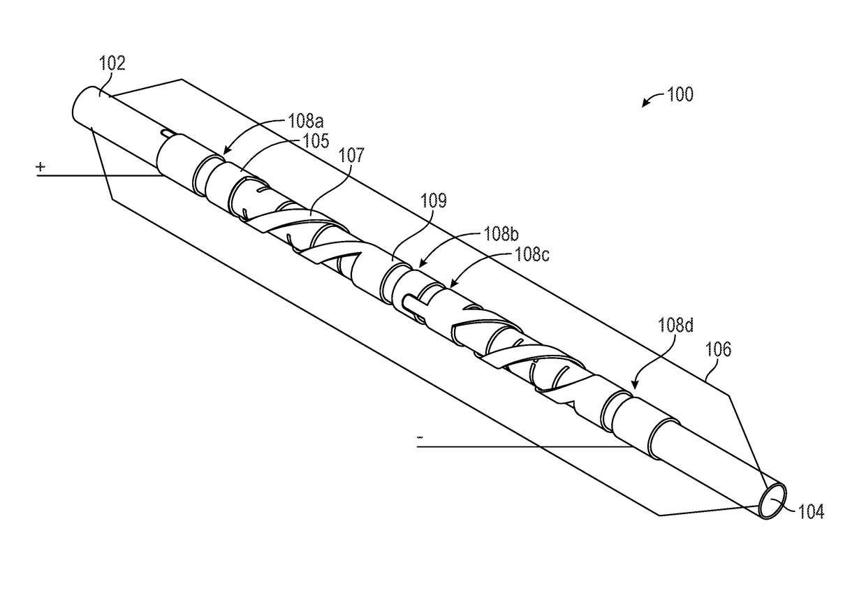
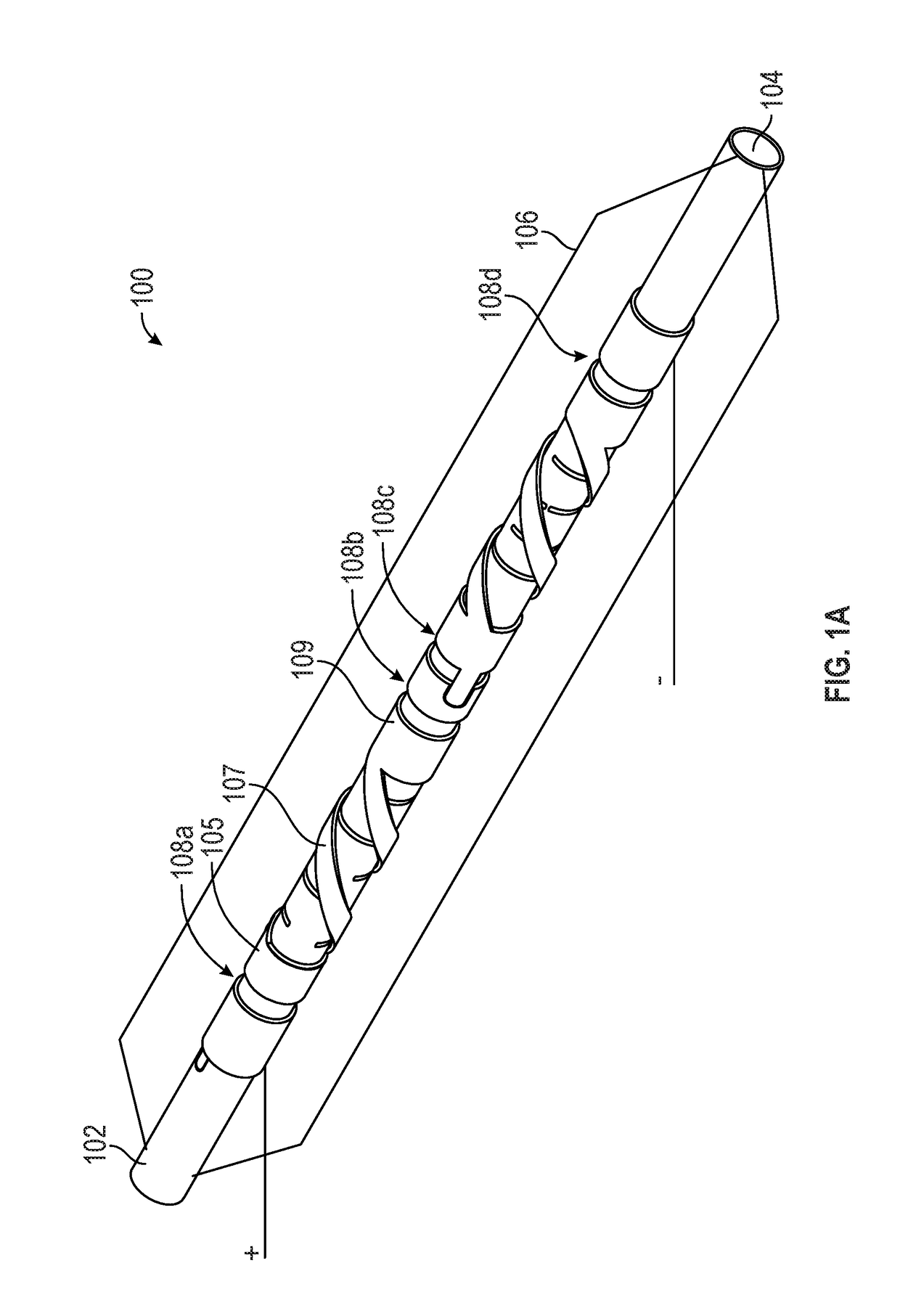
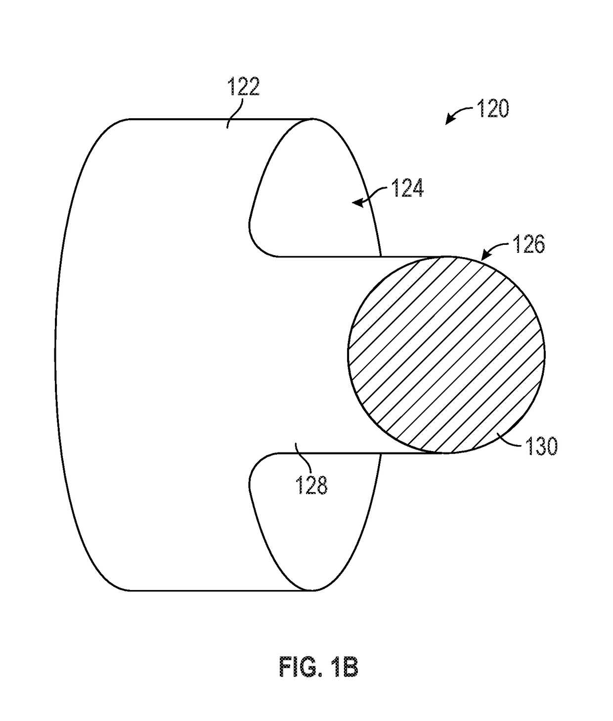
[0018]Described herein are electrodes for the generation of shock waves within vascular structures. One variation of a shock wave electrode pair comprises a first electrode that is circumferentially disposed over an outer surface of an elongate member and a second electrode also circumferentially disposed over the outer surface of the elongate member, where a spark gap may be formed at the narrowest separation distance between the two electrodes. The electrodes may be planar electrodes that are coplanar with each other (e.g., located along a single layer) over the outer surface of the elongate member (e.g., catheter). In some variations, the first electrode may have a recess (or protrusion) that corresponds with a protrusion (or groove) of the second electrode. The separation between the edge of the recess (or protrusion) of the first electrode and the edge of the protrusion (or recess) of the second electrode may be the shortest distance between the first and second electrodes, and...


PUM


Abstract

Disclosed herein shock wave catheters comprising one or more shock wave electrodes for cracking calcifications located within blood vessels. In some variations, a shock wave catheter has first and second shock wave electrodes each circumferentially disposed over the outer surface of the catheter. In certain variations, the first electrode has a recess and the second electrode has a protrusion that is received by the recess and a spark gap is located along the separation between the recess and the protrusion. The second electrode can also have a recess that receives a protrusion from a third shock wave electrode, where the separation between the second and third electrodes along the separation between the recess and the protrusion forms a second spark gap. A shock wave can be initiated across these spark gaps when a voltage is applied over the electrodes.

Description

CROSS-REFERENCE TO RELATED APPLICATIONS[0001]This application claims priority to U.S. Provisional Patent Application Ser. No. 62 / 257,141 entitled “SHOCK WAVE ELECTRODES,” filed on Nov. 18, 2015, which is hereby incorporated by reference in its entirety for all purposes.FIELD[0002]The present disclosure relates generally to shock wave electrodes, and, more specifically, to electrodes for the generation of shock waves within vascular structures.BACKGROUND[0003]Electrohydraulic lithotripsy has been typically used for breaking calcified deposits or “stones” in the urinary or biliary track. Recent work by the assignee shows that lithotripsy electrodes may similarly be useful for breaking calcified plaques in the wall of a vascular structure. Shock waves generated by lithotripsy electrodes may be used to controllably fracture a calcified lesion to help prevent sudden stress and injury to the vessel or valve wall when it is dilated using a balloon. A method and system for treating stenotic...

Claims


Application Information

Patent Timeline
Patent Type & Authority Applications(United States)
IPC IPC(8): A61B17/22
CPCA61B17/2202A61B2017/22025A61B2017/22061A61B2017/22001A61B2017/22021A61B17/22022A61B17/22004
Inventor NGUYEN, HOA D.ADAMS, JOHN M.
Owner SHOCKWAVE MEDICAL
Why Eureka
Try Eureka