
Image processing for spectral ct

a spectral ct and image processing technology, applied in image enhancement, instruments, applications, etc., can solve the problems of increasing the risk of cancer, increasing the noise of images, and blurring or un-sharp images

Active Publication Date: 2014-05-15
KONINKLIJKE PHILIPS ELECTRONICS NV
View PDF37 Cites 45 Cited by
  • Summary
  • Abstract
  • Description
  • Claims
  • Application Information

AI Technical Summary

Benefits of technology

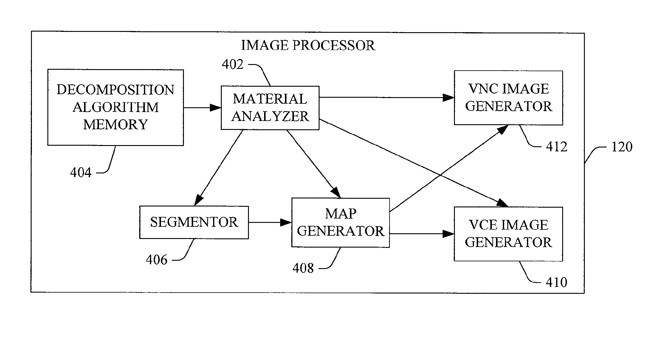
The patent describes a method for generating a map of calcium in bones using spectral images. The method involves reducing noise in the images and using a probability decomposition to create a map of calcium. The map is then improved by minimizing its total variation and creating a binary mask that separates bone and calcium based on the improved calcium map and a predetermined threshold. The technical effects of this method are the ability to accurately identify and segment bones and calcified structures in images, which can be useful in a variety of fields such as medical diagnosis or sports equipment design.

Problems solved by technology

Unfortunately, ionizing radiation may damage or kill cells and / or increase the risk of cancer.
However, the radiation dose for a particular imaging procedure cannot just be lowered as a lower dose leads to increased image noise and thus blurrier or un-sharp image.
Moreover, spectral CT images are already inherently noisier than conventional non-spectral images.
However, after administration of a contrast material, some patients experience idiosyncratic effects and certain patients may experience severe and potentially life-threatening allergic reactions.
Contrast material may also induce kidney damage, and some patients have developed an acute deterioration of their kidney function.
Unfortunately, as the contrast material volume increases, so does its associated risks.

Method used


Image

  • Image processing for spectral ct
  • Image processing for spectral ct
  • Image processing for spectral ct

Examples


Embodiment Construction

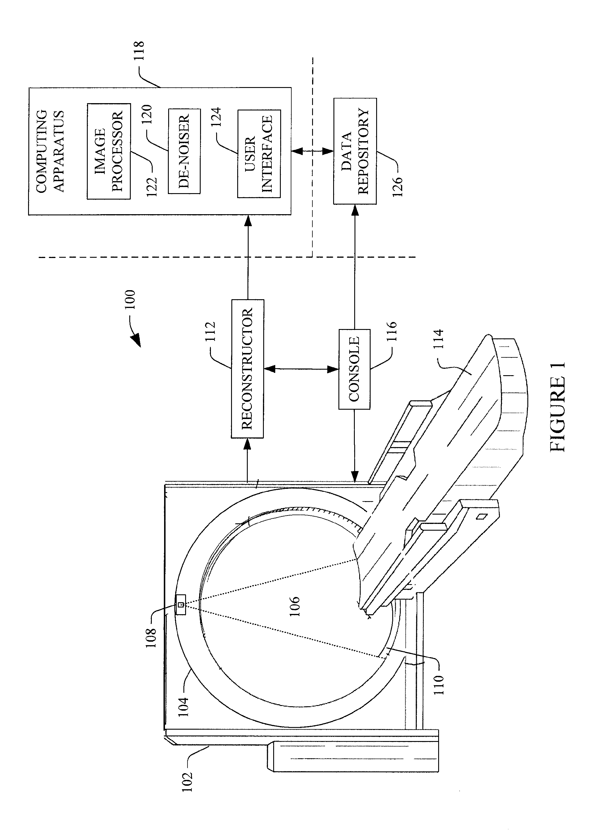
[0030]FIG. 1 illustrates an imaging system 100 such as a computed tomography (CT) scanner configured for spectral CT imaging. The imaging system 100 includes a stationary gantry 102 and a rotating gantry 104, which is rotatably supported by the stationary gantry 102. The rotating gantry 104 rotates around an examination region 106 about a longitudinal or z-axis.

[0031]The system 100 includes at least one radiation source 108, such as an x-ray tube, that is supported by the rotating gantry 104 and which rotates with the rotating gantry 104 about the examination region 106. The at least one radiation source 108 emits radiation that traverses the examination region 106. Where there are at least two radiation sources 108, each source can be configured to emit radiation having a different mean emission spectrum. Additionally or alternatively, one or more of the at least two sources 108 can be configured to controllably switch between at least two different emission voltages (kVp's) during...


PUM


Abstract

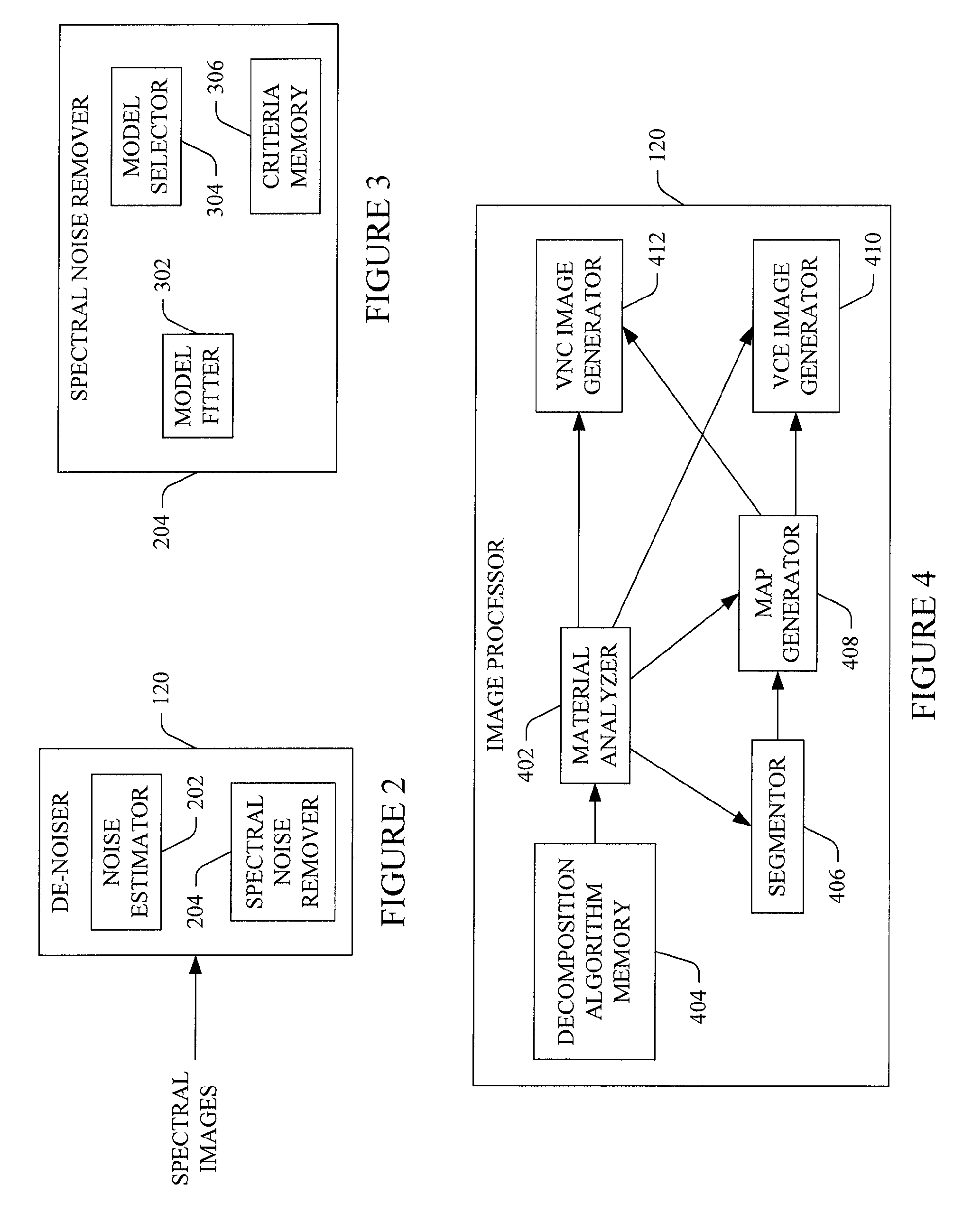
A method includes estimating structure models for a voxel(s) of a spectral image based on a noise model, fitting structure models to a 3D neighborhood about the voxel(s), selecting one of the structure models for the voxel(s) based on the fittings and predetermined model selection criteria, and de-noising the voxel(s) based on the selected structure model, producing a set of de-noised spectral images. Another method includes generating a virtual contrast enhanced intermediate image for each energy image of a set of spectral images corresponding to different energy ranges based on de-noised spectral images, decomposed de-noised spectral images, an iodine map, and a contrast enhancement factor; and generating final virtual contrast enhanced images by incorporating a simulated partial volume effect with the intermediate virtual contrast enhanced images. Also described herein are approaches for generating a virtual non-contrasted image, a bone and calcification segmentation map, and an iodine map for multi-energy imaging studies.

Description

FIELD OF THE INVENTION[0001]The following generally relates to computed tomography (CT) and more particularly to spectral CT.BACKGROUND OF THE INVENTION[0002]A CT scanner generally includes an x-ray tube that emits ionizing radiation that traverses an examination region and a portion of an object or subject therein and illuminates a detector array disposed across the examination region, opposite the x-ray tube. The detector produces projection data indicative of the detected radiation. The data can be reconstructed to generate volumetric image data indicative of the portion of the object or subject. With spectral CT, the projection data includes signals which are acquired concurrently and that correspond to different photon energy ranges. There are several approaches for performing spectral CT. For example, the CT scanner may include two or more sources, at least one source configured to switch between at least two different kVps, and / or a detector array with energy-resolving detect...

Claims


Application Information

Patent Timeline
IPC IPC(8): G06T5/00
CPCG06T5/002G06T2200/04G06T2207/10072G06T2207/30004A61B6/032A61B6/481A61B6/482A61B6/5258G06T5/70G06T5/00A61B6/5205G06T2207/10081G06T2207/30008
Inventor GOSHEN, LIRAN
Owner KONINKLIJKE PHILIPS ELECTRONICS NV
Learn More