Compression device for the limb

Active Publication Date: 2014-01-28
SWELLING SOLUTIONS
View PDF61 Cites 9 Cited by
  • Summary
  • Abstract
  • Description
  • Claims
  • Application Information

AI Technical Summary

Benefits of technology

[0018]Alternatively the cells can be constructed from an inner part joined to an outer part by side walls, the outer part then being joined to the sleeve. In such a construction the outer part and inner part can be made from layers of the same material which are joined together by side walls. A three layer assembly of this type has advantages over the two layer assembly described above in that the inner part and outer part of the cell can be the same material making the cell more likely to be airtight and the seal reliable. As the sleeve is not the outer part of the cell, the sleeve need not be made from an airtight material and can for instance be made of fabric. The three layer assembly also means that the welds used to join the cell parts together are not visible on the outer surface of the sleeve and the cells need not be attached to the sleeve over the whole of their surface. This means that it is possible to shape the sleeve to adapt more fully to the shape of the limb.
[0019]Preferably the sleeve is

Problems solved by technology

This in turn reduces the residence time for blood supplied to the lower limb and the severity of ischaemic episodes within the limb that can result in tissue breakdown.
The known devices apply pressure to the limb through a thick cuff or cuffs which affect patient mobility and are aesthetically unacceptable to many patients.
The pump that produces the compression is large and heavy and can supply fluid to the cuffs through many pipes.
These characteristics make the known devices unsuitable for domestic use.
It is believed that immediate mobilisation under compression post-surgery is beneficial in prevention of DVT, and existin

Method used


Image

  • Compression device for the limb
  • Compression device for the limb
  • Compression device for the limb

Examples


example 1

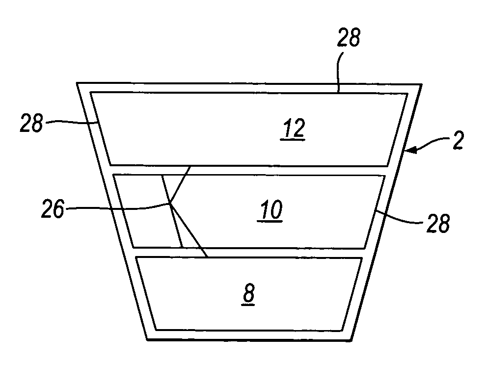
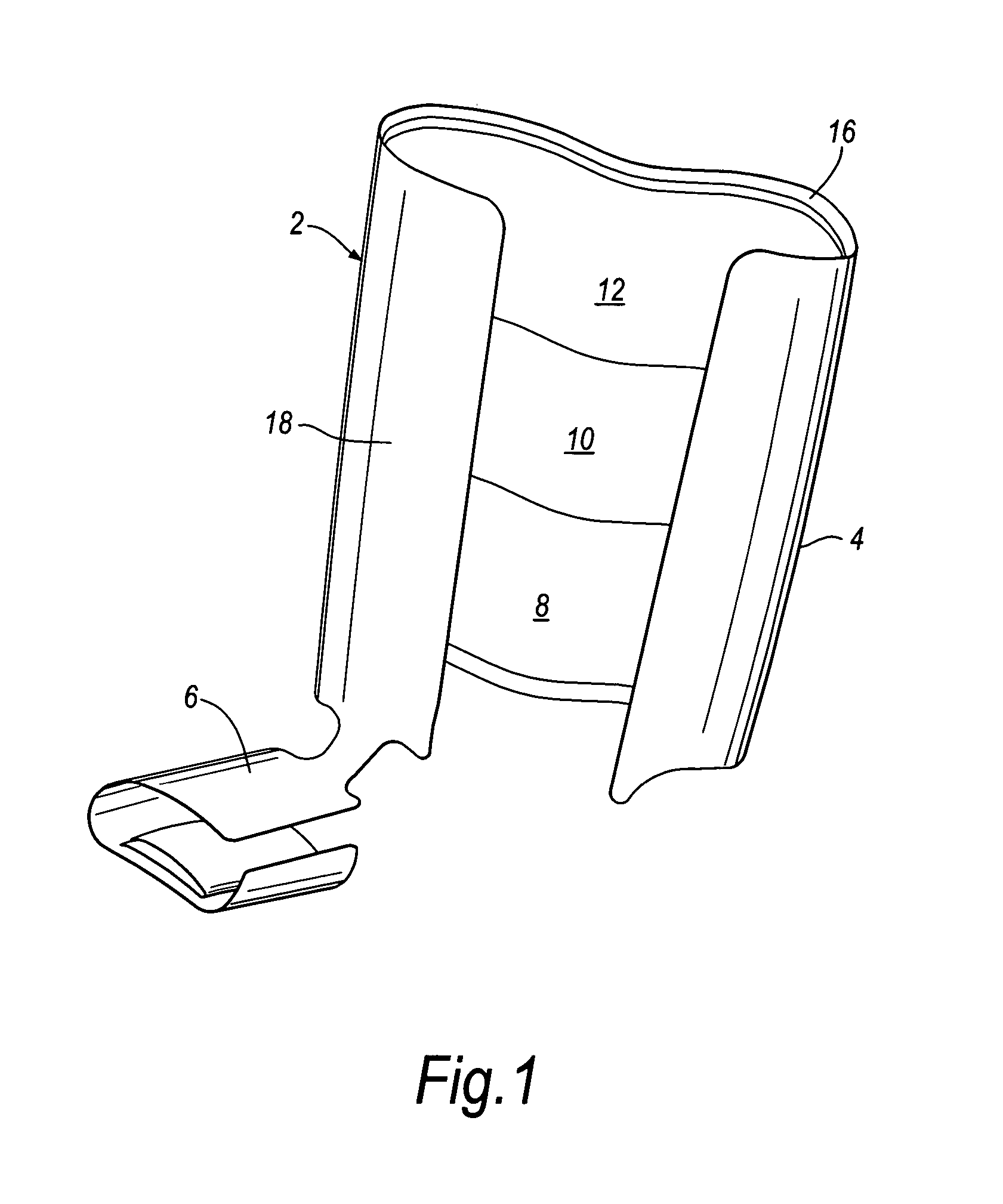
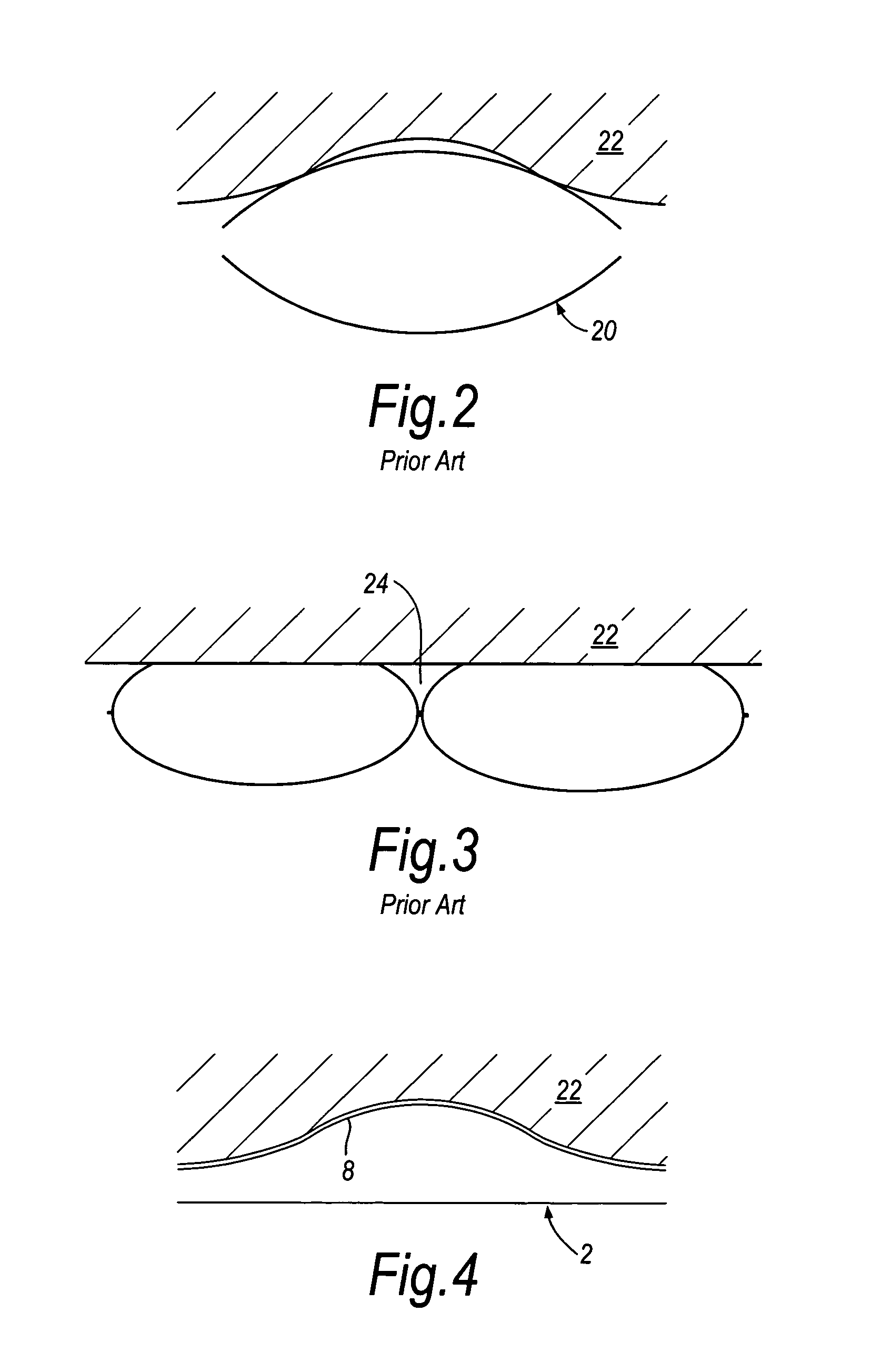
[0042]Two adjacent cells of a device similar to that shown in FIG. 1 were the subject of a finite element analysis to simulate the pressure profile experienced by the limb when such a device is used. The analysis was conducted assuming a cell construction such as that used in FIG. 3 and compared to a cell construction such as that used in FIG. 7 where the cells have side walls. The analysis was conducted using Abacus UK Ltd software version 6.41. FIG. 11 shows the profile generated for the device of FIG. 3 where the cells are of a simple bag-like construction. The pressure distribution is uneven showing peaks at the edge of each cell which fall rapidly to a large area of zero pressure between the cells. The pressure is also depressed at the centre of each cell. By contrast the pressure distribution shown in FIG. 12 for the device of FIG. 7 is much more even with an even pressure across the cell width and only a small area of zero pressure between the cells. These figures show the ad...


PUM


Abstract

A compression device for a limb has a sleeve adapted to surround the limb. The sleeve has an inelastic layer and a cell constructed from an inner part joined to an outer part by one or more side walls. This construction provides a cell with a box-like configuration so that the inner part conforms to the shape of the limb, providing an even pressure to the limb, when the cell is inflated.

Description

[0001]This invention relates to a compression device for the limb and particularly to a device for use on the leg. The device is particularly suited for use in the type of compression therapy used in the treatment of venous leg ulcers.BACKGROUND OF THE INVENTION[0002]Various compression devices are known for applying compressive pressure to a patient's limb. These types of devices are used to assist mainly in the prevention of deep vein thrombosis (DVT), vascular disorders and the reduction of oedema. Prior art devices are adapted for use in a hospital setting in which they are used predominantly for the prevention of DVT in patients with a high risk for developing the same. U.S. Pat. No. 5,117,812, U.S. Pat. No. 5,022,387 and U.S. Pat. No. 5,263,473 (The Kendall Company), U.S. Pat. No. 6,231,532 (Tyco International Inc), U.S. Pat. No. 6,440,093 (McEwen et al) and U.S. Pat. No. 6,463,934 (Aircast Inc) disclose such devices.[0003]Compression therapy is used in the treatment of venous...

Claims


Application Information

Patent Timeline
IPC IPC(8): A61H19/00A61H23/04A61H7/00
CPCA61H9/0078A61H2205/10A61H2209/00A61H9/005
Inventor LINNANE, PATRICK G.TABRON, IAN S.FERNADEZ, ARSENIOBOSTROM, ANDERS L.HANSEN, PETER L.MIRZA, MUHAMMED SAILM
Owner SWELLING SOLUTIONS
Why Eureka
Try Eureka