
Aerosol-generating apparatus, film-forming apparatus, and aerosol-generating method

a technology of aerosol and film, which is applied in the field of aerosol generation apparatus and film, can solve the problems of increasing the particle size of material particles, affecting the long-term stable generation, and a certain limit to suppress so as to achieve stable generation or production of aerosol over a long period of time, and reducing the aggregation of material particles

Inactive Publication Date: 2014-01-28
BROTHER KOGYO KK
View PDF16 Cites 1 Cited by
  • Summary
  • Abstract
  • Description
  • Claims
  • Application Information

AI Technical Summary

Benefits of technology

The present invention relates to an apparatus and method for generating aerosol. The technical effect of the invention is to reduce the aggregation of material particles in a powder-accommodating chamber, leading to a stable production of aerosol over a long period of time.

Problems solved by technology

A problem has been hitherto pointed out about the fact that the material particles are aggregated or coagulated and the particle sizes of the material particles are increased when the aerosol-generating apparatus is used for a long period of time.
However, whether the gas flow rate of the carrier gas is large or small exerts a serious influence on the coating characteristic of the material particles with which the substrate is to be coated.
Therefore, there is obviously a certain limit to suppress the aggregation of the material particles by adjusting the agitation state and / or the fluidization state of the powder by adjusting the flow rate of the carrier gas.
Any trouble arises in the long-term stable generation of the aerosol to be brought about by the aerosol-generating apparatus.
In other words, in the case of the conventional aerosol-generating apparatus, it is extremely difficult to maintain a constant concentration of the material particles in the aerosol for a long period of time.
This fact causes a serious obstacle against the practical use (industrial application) of the film-forming apparatus based on the use of the AD method.

Method used


Image

  • Aerosol-generating apparatus, film-forming apparatus, and aerosol-generating method
  • Aerosol-generating apparatus, film-forming apparatus, and aerosol-generating method
  • Aerosol-generating apparatus, film-forming apparatus, and aerosol-generating method

Examples


first embodiment

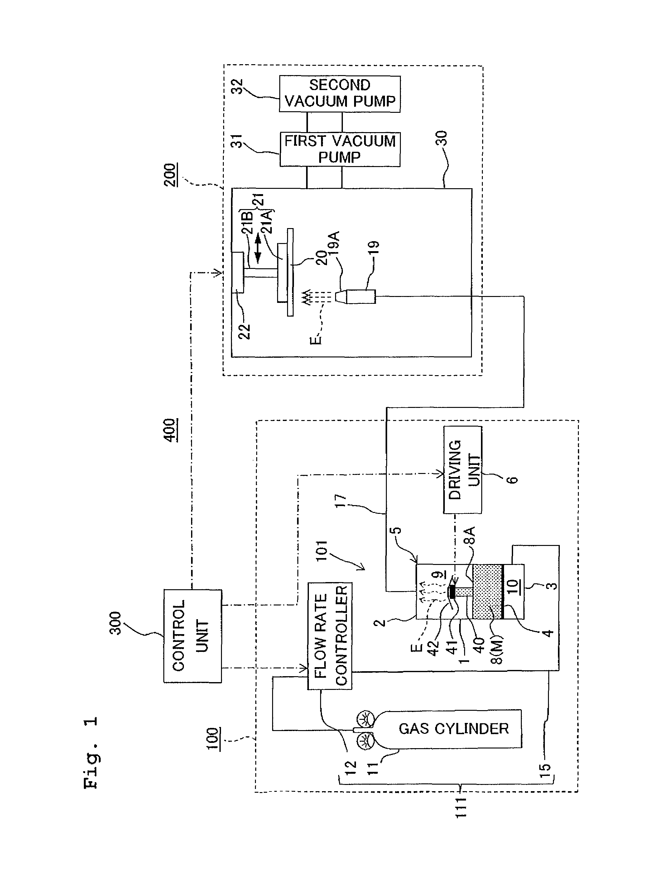
[0083]FIG. 1 schematically shows an example of a film-forming apparatus equipped with an aerosol-generating apparatus (aerosol-generating section) according to a first embodiment of the present invention. In FIG. 1 (as well as in the first, second, third, and fourth embodiments as described later on), the internal situations of an accommodating vessel or container 5 and a film-forming chamber 30 are shown.

[0084]As shown in FIG. 1, a film-forming apparatus 400 used for the AD method includes an aerosol-generating mechanism 100 which generates the aerosol E by mixing a carrier gas and material particles M contained in a powder 8, a film-forming mechanism (film-forming section) 200 which forms a film of the material particles M by jetting the aerosol E generated by the aerosol-generating mechanism 100 toward a substrate 20, and a control unit (control section, controller) 300 which controls the operations of the aerosol-generating mechanism 100 and the film-forming mechanism 200.

[0085]...

second embodiment

[0128]FIG. 3 schematically shows main components of an exemplary arrangement of an aerosol-generating apparatus according to a second embodiment of the present invention.

[0129]In the aerosol-generating apparatus 301 of this embodiment, the flow passage member 40 and the penetrating pore member 4 of the aerosol-generating apparatus 101 of the first embodiment are changed as follows.

[0130]As shown in FIG. 3, a funnel-shaped (hopper-shaped) penetrating pore member 4A is provided in the accommodating vessel 5 to compart the internal space thereof into two chambers. The upper space, which is included in the internal space of the accommodating vessel 5 and which is comparted by the penetrating pore member 4A, functions as the powder-accommodating chamber 9 to accommodate the powder 8 of the material particles M. The lower space functions as the carrier gas-introducing chamber 10 to introduce the carrier gas into the powder-accommodating chamber 9.

[0131]The penetrating pore member 4A has a...

third embodiment

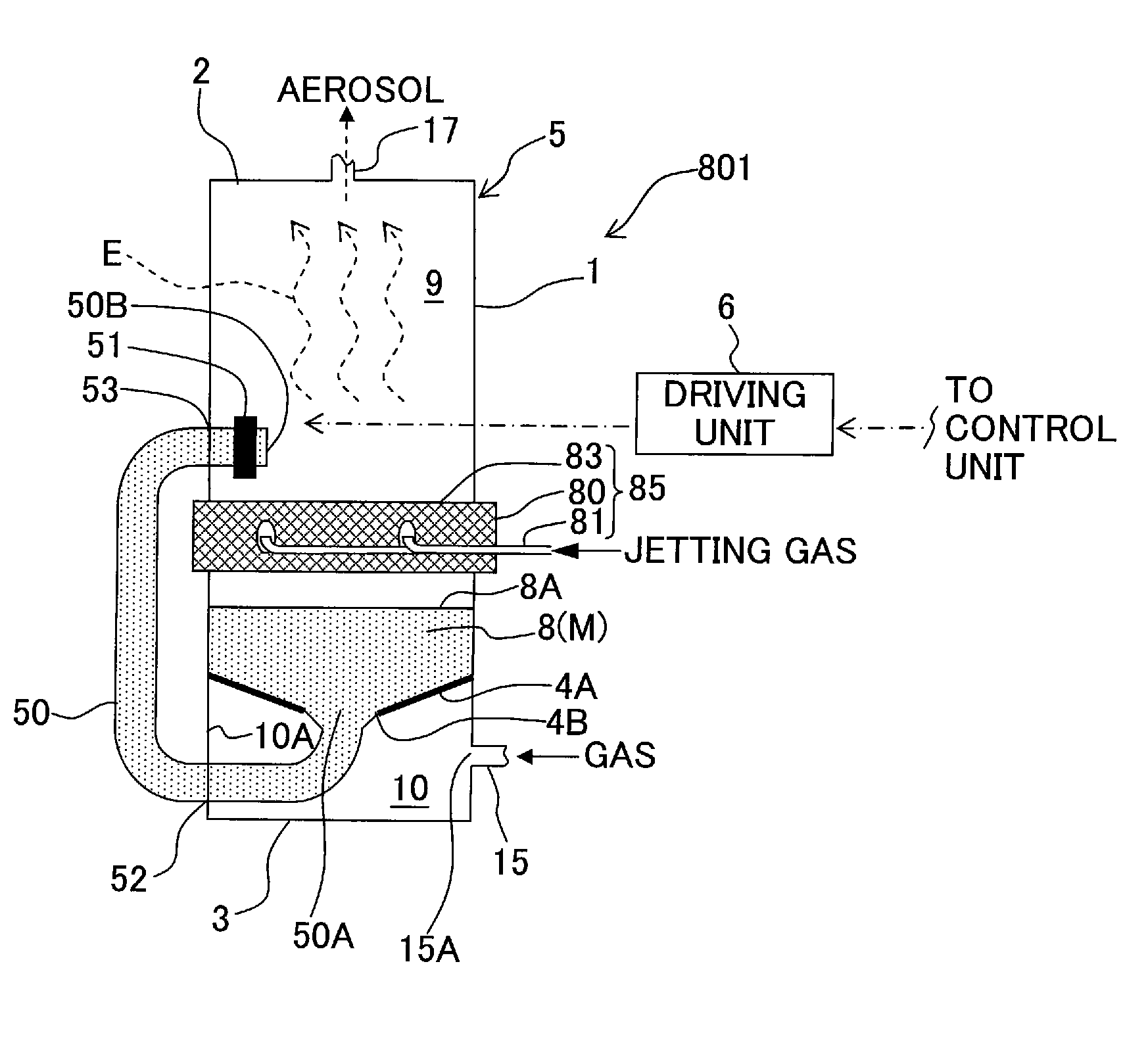
[0140]FIG. 4 schematically shows main components of an exemplary arrangement of an aerosol-generating apparatus according to a third embodiment of the present invention. The aerosol-generating apparatus 401 of this embodiment differs in that a flow passage member 60 thereof is changed as follows as compared with the flow passage member 40 of the aerosol-generating apparatus 101 of the first embodiment.

[0141]The flow passage member 60 of the aerosol-generating apparatus 401 constitutes the powder flow passage for transporting the powder 8. In this embodiment, the flow passage member 60 is a cylindrical piping made of resin (for example, made of acrylic resin). As shown in FIG. 4, the flow passage member 60 has a substantially U-shaped form, which is arranged so that the flow passage member 60 protrudes in the horizontal direction from the inside to the outside of the accommodating vessel 5. The flow passage member 60 has an upper intersecting section 63 which intersects the inner wal...


PUM


Abstract

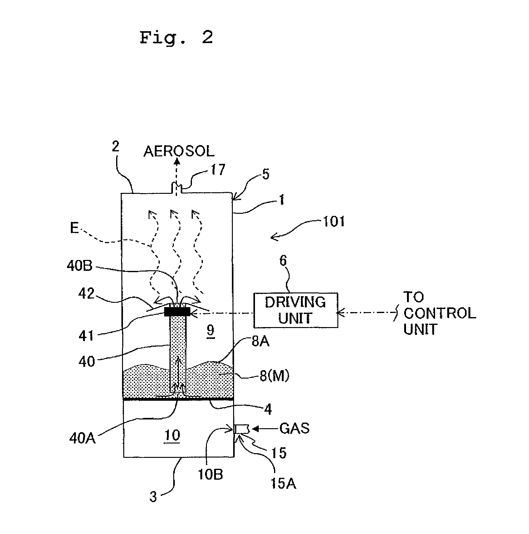
An aerosol-generating apparatus includes a body having a powder-accommodating chamber which accommodates a powder of the material particles, and an introducing port via which the carrier gas is introduced into the powder-accommodating chamber; a powder flow passage which has an inlet opening and an outlet opening both of which are open in the powder-accommodating chamber, the inlet opening being positioned at a position lower than that of the outlet opening in a vertical direction; and a transport mechanism which transports the powder in a direction directed from the inlet opening to the outlet opening of the powder flow passage. Accordingly, the aerosol-generating apparatus is provided, which makes it possible to stably produce the aerosol over a long period of time by appropriately reducing the aggregation of the material particles accommodated in the powder-accommodating chamber.

Description

CROSS REFERENCE TO RELATED APPLICATION[0001]The present application claims priorities from Japanese Patent Application Nos. 2007-172028 and 2007-341564 filed on Jun. 29, 2007 and Dec. 29, 2007, respectively, the disclosures of which are incorporated herein by reference in their entirety.BACKGROUND OF THE INVENTION[0002]1. Field of the Invention[0003]The present invention relates to an aerosol-generating apparatus, a film-forming apparatus, and an aerosol-generating method.[0004]2. Description of the Related Art[0005]The aerosol deposition method (hereinafter referred to as “AD method”) is such a technique that material particles, which are converted into an aerosol by being mixed with a carrier gas, are introduced into a reduced pressure space in a film-forming chamber, and the material particles are jetted from a nozzle toward a substrate at a high velocity on the basis of a differential pressure between the internal pressure of the film-forming chamber and the internal pressure of...

Claims


Application Information

Patent Timeline
Patent Type & Authority Patents(United States)
IPC IPC(8): B05C11/00B05B7/00B05D1/12
CPCB05B7/1445
Inventor NORIMATSU, TAKAHIRO
Owner BROTHER KOGYO KK
Learn More