Method and system for providing a magnetic read transducer having a bilayer magnetic seed layer

a technology of magnetic read transducer and seed layer, which is applied in the field of providing a magnetic read transducer having a bilayer magnetic seed layer, can solve the problems of adversely affecting the performance of the conventional transducer, generating more noise, and affecting the sensor b>

Active Publication Date: 2014-01-28
WESTERN DIGITAL TECH INC
View PDF5 Cites 152 Cited by
  • Summary
  • Abstract
  • Description
  • Claims
  • Application Information

AI Technical Summary

Problems solved by technology

This would adversely affect performance of the conventional transducer 10.
The magnetostriction may adversely affect sensor 20 performance.
For example, more noise may be generated.
This magnetostriction may also induce an undesired magnetic anisotropy perpendicular to the ABS.
The conventional shield 12 may thus become unstable during recording or in the presence of external stray fields.
As a result, the free layer response amplitude, asymmetry, and noise are adversely affected.
Thus, the conventional read transducer 10 may not function as desired at higher recording densities.

Method used


Image

  • Method and system for providing a magnetic read transducer having a bilayer magnetic seed layer
  • Method and system for providing a magnetic read transducer having a bilayer magnetic seed layer
  • Method and system for providing a magnetic read transducer having a bilayer magnetic seed layer

Examples


Embodiment Construction

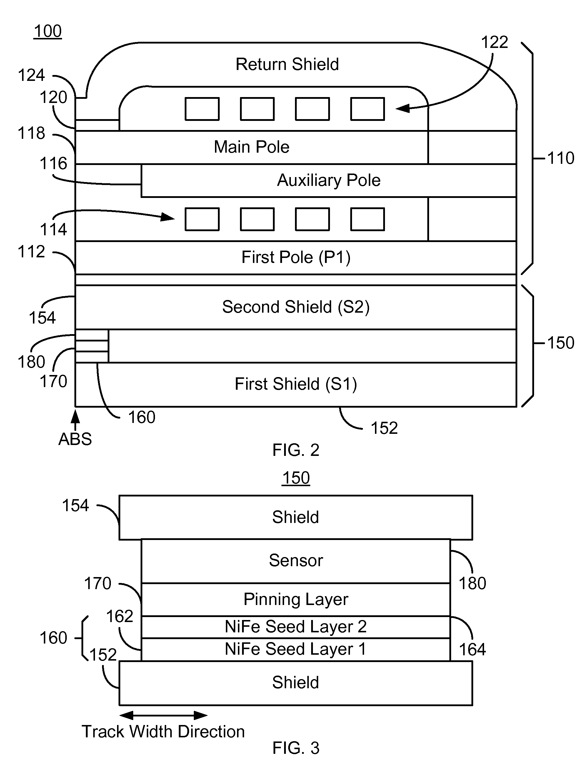
[0014]FIG. 2 depicts a magnetic head 100. FIG. 2 is not to scale and not all components of the magnetic head 100 are shown. The magnetic head 100 is a merged head that includes a magnetic write transducer 110 and a magnetic read transducer 150. In other embodiments, the read transducer 150 and write transducer 110 may also be in separate heads. The magnetic head 100 resides on a slider and is typically one of many magnetic heads in a disk drive and used to write to and read from a media (not shown). The write transducer 110 includes a first pole 112, auxiliary pole 116, main pole 118, write gap 120, coils 114 and 122, and return shield 124. However, in another embodiment, the write transducer 110 includes other and / or different components. In addition, one or more portions of the write transducer 110 might be omitted in various embodiments.

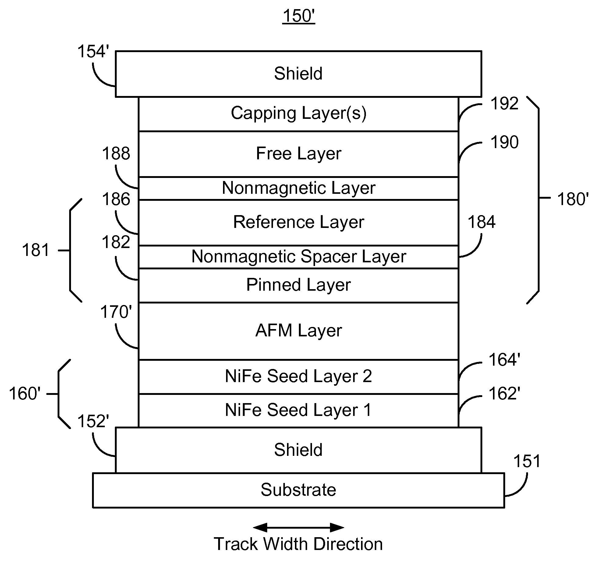
[0015]The read transducer 150 includes shields 152 and 154, bilayer magnetic seed layer 160, pinning layer 170, and sensor 180. The sensor 180 ma...


PUM

PropertyMeasurementUnit
thicknessaaaaaaaaaa
thicknessaaaaaaaaaa
thicknessaaaaaaaaaa

Abstract

A method and system for providing a magnetic read transducer is described. The magnetic read transducer includes a bilayer magnetic seed layer, an antiferromagnetic (AFM) layer, and a read sensor. The bilayer magnetic seed layer includes a Ni1-xFex layer and a Ni1-yFey layer on the Ni1-xFex layer, where x is at least 0.3 and not more than 1 and where y is not more than 0.19. The AFM layer resides on the bilayer magnetic seed layer. The read sensor is on the AFM layer.

Description

CROSS REFERENCE TO RELATED APPLICATIONS[0001]This application is a continuation of co-pending U.S. patent application Ser. No. 13 / 297,204, filed on Nov. 15, 2011, which is hereby incorporated by reference in its entirety.BACKGROUND[0002]FIG. 1 depicts a portion of a conventional magnetic transducer 10, such as a conventional read transducer, as viewed from the air-bearing surface (ABS). The conventional transducer 10 includes a conventional bottom shield 12, a nonmagnetic underlayer 13, conventional NiFe seed layer 14, conventional nonmagnetic seed layer 16, conventional antiferromagnetic (AFM) layer 18, conventional sensor 20, conventional capping layer 36, and conventional top shield 40. The conventional shields 12 and 40 typically include NiFe and are formed by plating. The conventional underlayer 13 typically includes materials such as Ta, CoFeB, and NiFeB. The conventional nonmagnetic seed layer 16 is typically Ru or NiFeCr.[0003]The conventional sensor 20 is in a current-perpe...

Claims


Application Information

Patent Timeline
Patent Type & Authority Patents(United States)
IPC IPC(8): G11B5/39
CPCH01F10/3272H01F10/30G01R33/093H01F10/3254G11B5/3929G11B5/3906
Inventor LENG, QUNWENCHEN, LAURENCE L.GUO, YIMINZHENG, YUANKAIPAKALA, MAHENDRA
Owner WESTERN DIGITAL TECH INC
Why Eureka
Try Eureka