Low-profile loudspeaker driver and enclosure assembly

a low-profile, loudspeaker technology, applied in the field of low-profile loudspeaker drivers, can solve the problems of aesthetically disconcerting and out of place, speaker protruding or projecting away, and high-fidelity loudspeaker systems are typically relatively large and bulky, so as to improve heat dissipation, enhance the low profile of the enclosure, and reduce the depth

Active Publication Date: 2014-01-28
DEFINITIVE TECH
View PDF3 Cites 15 Cited by
  • Summary
  • Abstract
  • Description
  • Claims
  • Application Information

AI Technical Summary

Benefits of technology

[0009]Accordingly, it is an object of the present invention to overcome the above mentioned difficulties by providing a low-profile loudspeaker system having a driver mounted in an enclosure having a reduced front-to-back dimension while maintaining high performance system audio fidelity.
[0012]The loudspeaker system driver motor magnetic circuit incorporates a low-profile cup-shaped pot having an upper rim which surrounds and is spaced from the voice coil carried by the coil former. A permanent magnet is secured to the bottom wall of the pot, with a suitable pole piece being mounted on the magnet and extending into the coil former. The pole piece cooperates with the rim of the pot to form a magnetic gap, with the voice coil being movable within the gap to drive the diaphragm in known manner. The bottom of the pot extends into and through a corresponding aperture in the rear panel of the enclosure to further reduce the depth required for the enclosure, thereby enhancing the low profile of the enclosure.
[0013]Since current flow in the voice coil for driving the diaphragm can produce a considerable amount of heat, the location of the pot in the rear panel aperture helps to cool the driver. To improve heat dissipation, the pot is surrounded by a thermally conductive sleeve which is part of the support basket and which centers and secures the driver in the rear panel and provides a thermal path from the pot to the panel by way of a thermally conductive gasket. In the preferred form of the invention, the driver is mounted within a loudspeaker enclosure that is fabricated from a rigid, thermally conductive material such as aluminum, which serves not only as a heat radiator, but which provides a solid, vibration-free environment. The gasket which secures the driver in the rear panel aperture also serves to seal the enclosure for improved sound quality.
[0014]The low-profile enclosure of the present invention may incorporate one or more loudspeakers constructed in the manner described above, which may serve as acoustical woofers having a wide frequency response. In one embodiment, the enclosure may be elongated in shape, carrying, for example, two woofer loudspeakers and two mid-range speakers mounted in a row with one or more conventional tweeters, and with the face of the enclosure covered by a suitable screen, or grille. Using the above-described driver construction for the woofers, and for the mid-range speakers if desired, the resulting enclosure will have thickness of 1.5 inches. When the speaker system of the present invention is mounted on a user's wall, the total installed on-wall depth of the speaker system is not more than 1.6 inches or forty millimeters (40 mm). Other speaker configurations within enclosures of various shapes may be used, while retaining the low profile thickness, to provide an aesthetic match for a thin-screen television or other display unit, while providing high quality sound reproduction.

Problems solved by technology

High fidelity loudspeaker systems are typically relatively large and bulky, since large cabinet or enclosure volumes provide greater efficiency and bass extension, among other benefits.
If a traditional high fidelity loudspeaker system is mounted on a wall, the speaker protrudes or projects away from its wall mount a considerable distance and as a consequence appears aesthetically displeasing and out of place, particularly when attached on the wall near a video display.
Part of the problem with traditional loudspeaker system designs arises from using enclosures having dynamic loudspeaker drivers, where the largest driver's component parts are aligned along a central axis, coaxially with a voice coil in such a way that the driver motor structure projects back from the front of the loudspeaker enclosure by a significant depth.
Although such loudspeaker systems perform well acoustically, they do not match the sleek appearance of modern “flat panel” video displays.

Method used


Image

  • Low-profile loudspeaker driver and enclosure assembly
  • Low-profile loudspeaker driver and enclosure assembly
  • Low-profile loudspeaker driver and enclosure assembly

Examples


Embodiment Construction

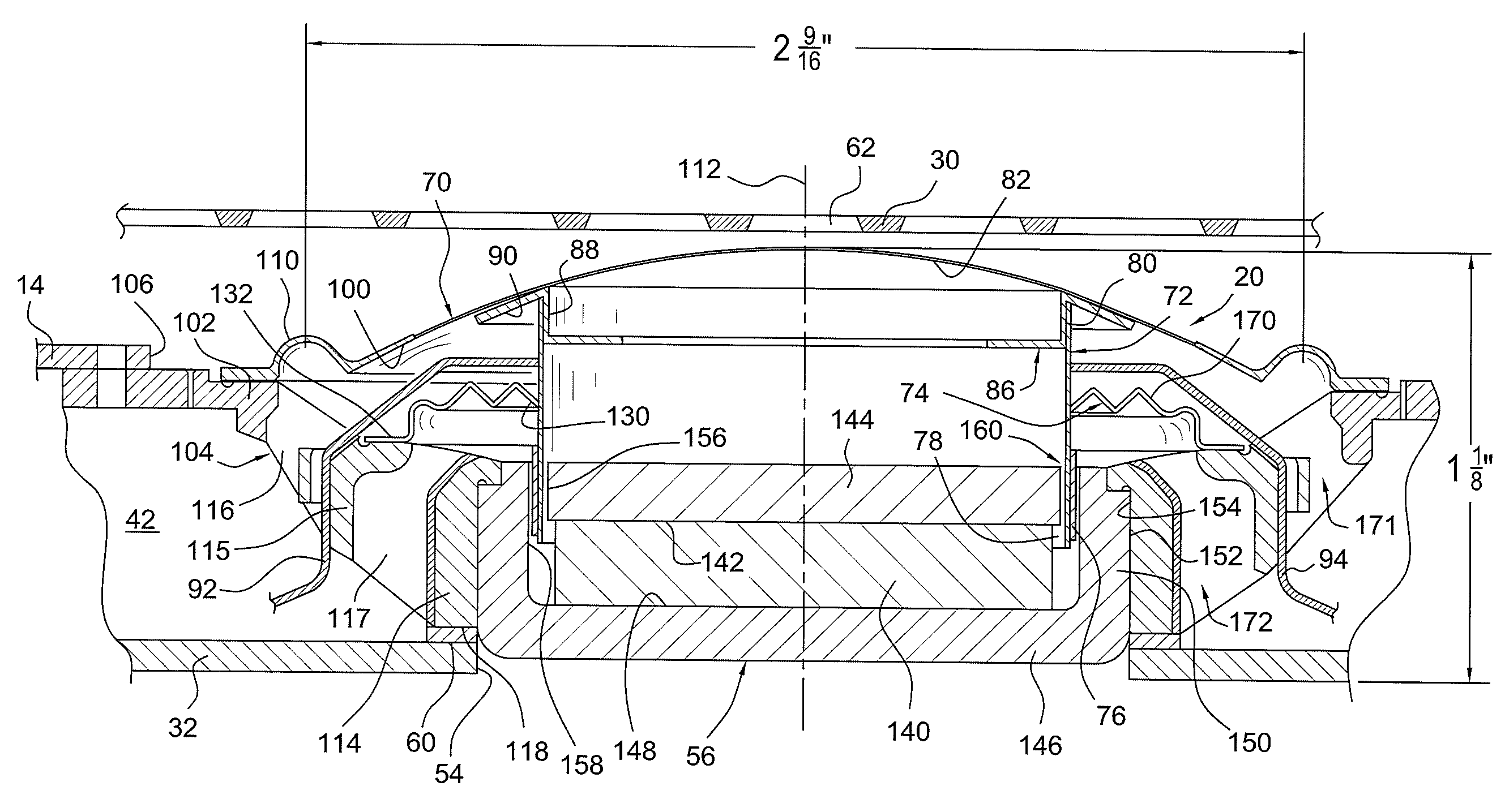
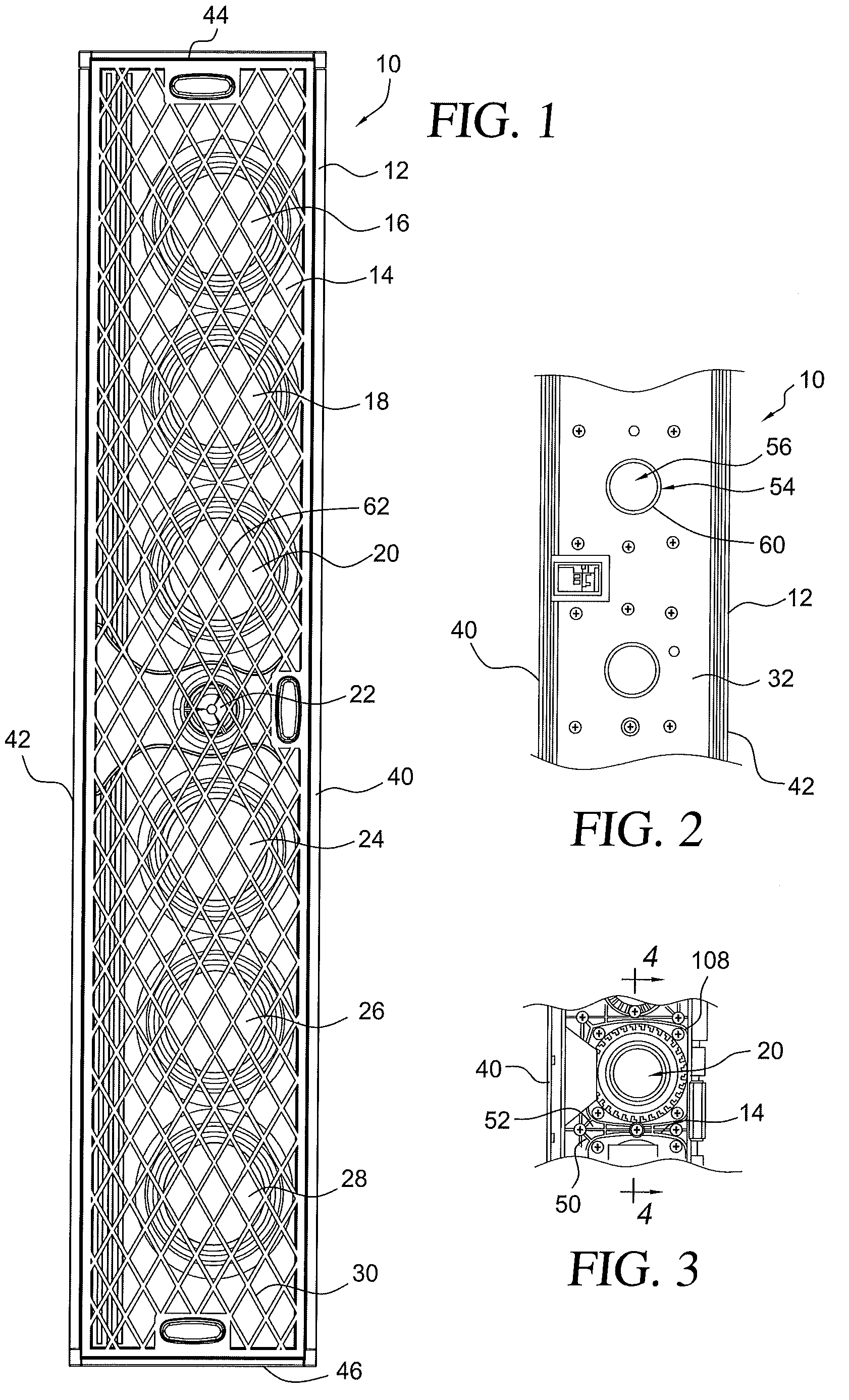
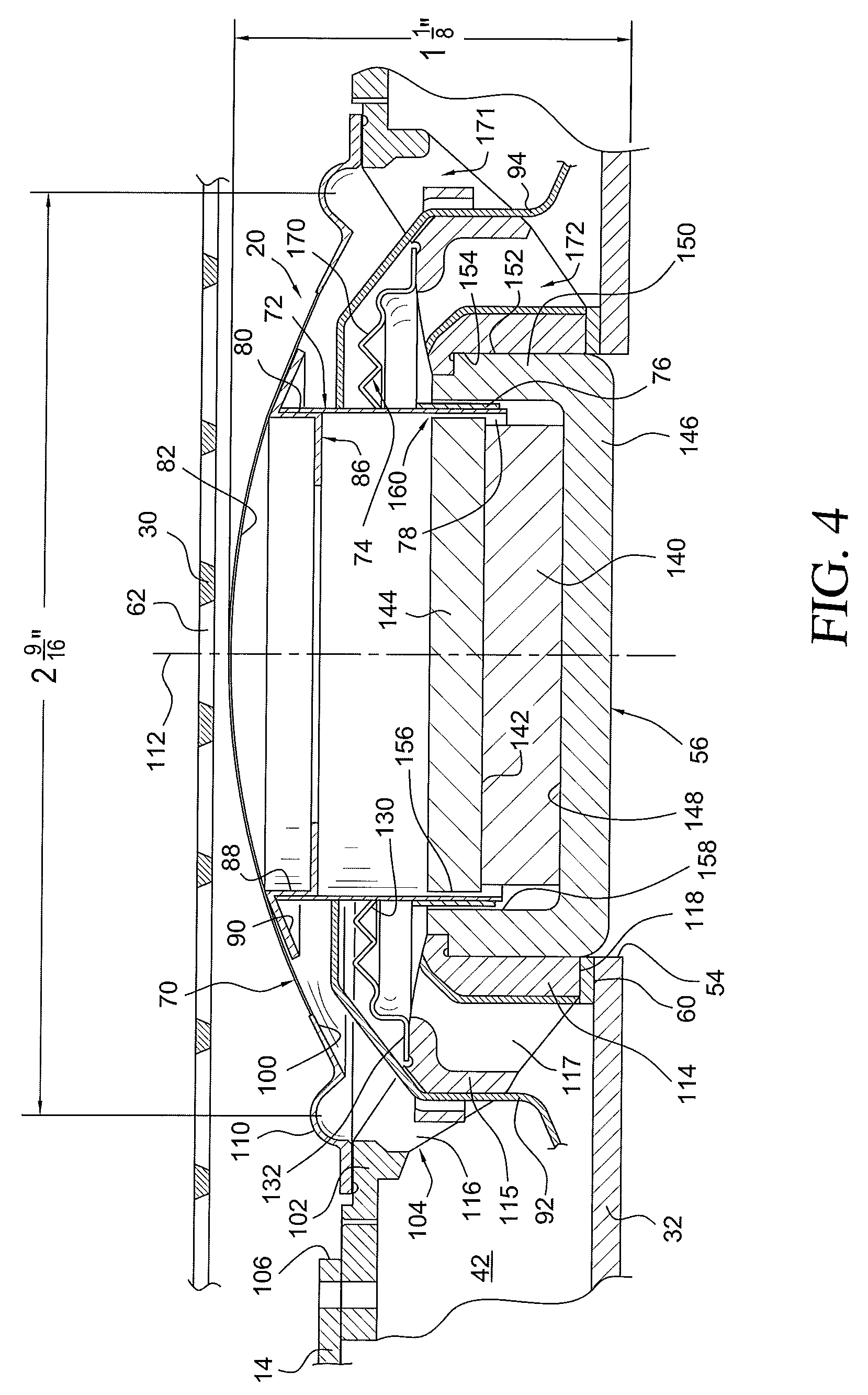
[0026]Turning now to a more detailed description of the present invention, the Figures illustrate specific preferred loudspeaker structural embodiments and mounting methods for the low-profile loudspeaker driver and enclosure assembly of the present invention. As described above, and as illustrated in the embodiment of FIGS. 1-5, a low-profile loudspeaker driver and enclosure assembly, or loudspeaker system 10, constructed in accordance with the present invention may include an elongated, rectangular cabinet, or enclosure, 12 having a front panel, face plate or baffle 14 upon which are mounted a plurality of loudspeaker transducers. In this illustration, seven loudspeaker transducers or drivers 16, 18, 20, 22, 24, 26, and 28 are aligned along the length of the enclosure, with transducer 22 being illustrated as a tweeter and the remaining transducers being midrange or woofer transducers, it being understood that a different number or mix of transducers may be used and that they may b...


PUM

PropertyMeasurementUnit
depthaaaaaaaaaa
thicknessaaaaaaaaaa
thicknessaaaaaaaaaa

Abstract

A high fidelity, low-profile loudspeaker assembly includes an enclosure having a rear panel which is highly thermally conductive. At least one speaker driver is mounted in the enclosure, the driver including a forwardly facing diaphragm driven by a voice coil former carrying a voice coil, and a rearwardly extending motor structure. An aperture is provided in the rear panel to receiving the driver's motor structure, and a thermally conductive gasket seals the rear panel aperture around cup to provide a thermal path from the driver motor to the rear panel for cooling the driver. On one driver embodiment, a generally dome-shaped annular spider surrounds and supports the voice coil former, the spider being connected at its inner periphery to the approximate vertical midpoint of the voice coil former.

Description

[0001]This application claims priority to and benefit of Provisional Application No. 61 / 291,855, filed Jan. 1, 2010, and entitled “Low-Profile Loudspeaker Driver and Enclosure Assembly”, the entire disclosure of which is hereby incorporated by reference.BACKGROUND OF THE INVENTION[0002]1. Field of the Invention[0003]The present invention relates to loudspeaker systems configured for use with wall-mounted flat panel displays such as video screens, and more particularly to wall mountable full range high fidelity loudspeaker enclosures having a low profile.[0004]2. Discussion of the Prior Art[0005]Modern flat-panel televisions and other video displays that are designed to be mounted on walls typically have very low-profile, ultra-thin screens, some of which may project away from the surface of a wall on which it is mounted by less than two inches. Traditional loudspeaker systems that are often used with such display devices to provide enhanced sound quality, are very much like traditio...

Claims


Application Information

Patent Timeline
Patent Type & Authority Patents(United States)
IPC IPC(8): H04R1/20H05K5/00
CPCH04R5/02Y10T29/4957
Inventor GLADWIN, TIMOTHY, A.
Owner DEFINITIVE TECH
Why Eureka
Try Eureka