Tulip contact and electrical contact system for switching device

a switching device and contact mechanism technology, applied in the direction of coupling contact members, coupling device connections, contacts heating/cooling, etc., can solve the problems of low heat generation, low heat ventilation, and low effective contact area of tulip contacts, so as to improve heat ventilation, reduce heat generation, and improve conductivity

Active Publication Date: 2014-02-04
ABB (SCHWEIZ) AG
View PDF21 Cites 7 Cited by
  • Summary
  • Abstract
  • Description
  • Claims
  • Application Information

AI Technical Summary

Benefits of technology

[0008]To overcome above shortcomings, the main purpose of the present invention is to provide a tulip contact and electrical contact system with tulip contact for switching device which possess qualities such as better conductivity, lower heat generation, better heat ventilation, stronger structure and higher reliability. The tulip contact and electrical contact system of the present invention can withstand high electrical current. Furthermore, it is easy to install.
[0009]According to one aspect of the invention, a tulip contact for switching device is provided. The tulip contact comprises a plurality of contact fingers and these contact fingers fall into outer contact fingers and inner contact fingers. The cross-section formed by said plurality of outer contact fingers is complimentary to the cross-section of the outer surface of fixed contact, so that the contact surface of each of these contact fingers can contact the outer surface of fixed contact; and the cross-section formed by said plurality of inner contact fingers is complimentary to the cross-section of the inner surface of fixed contact, so that the contact surface of each of these contact fingers can contact the inner surface of fixed contact.

Problems solved by technology

But this tulip contact does not have a large effective contact area.
This tulip contact has the disadvantage that its structure is not very firm.
In addition to above mentioned shortcomings of the traditional tulip contacts, all these tulip contacts do not possess such most important qualities as high electric conductivity, low heat generation and high heat ventilation.

Method used


Image

  • Tulip contact and electrical contact system for switching device
  • Tulip contact and electrical contact system for switching device
  • Tulip contact and electrical contact system for switching device

Examples


Embodiment Construction

[0032]With reference to the above-mentioned figures, preferred embodiments of the present invention are provided.

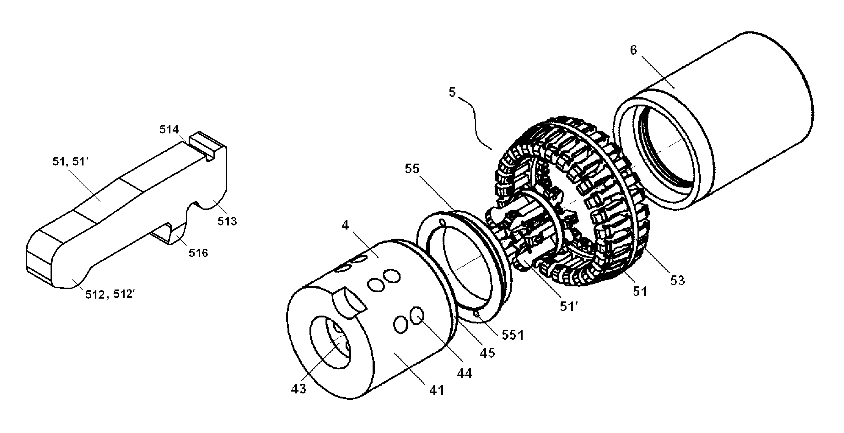
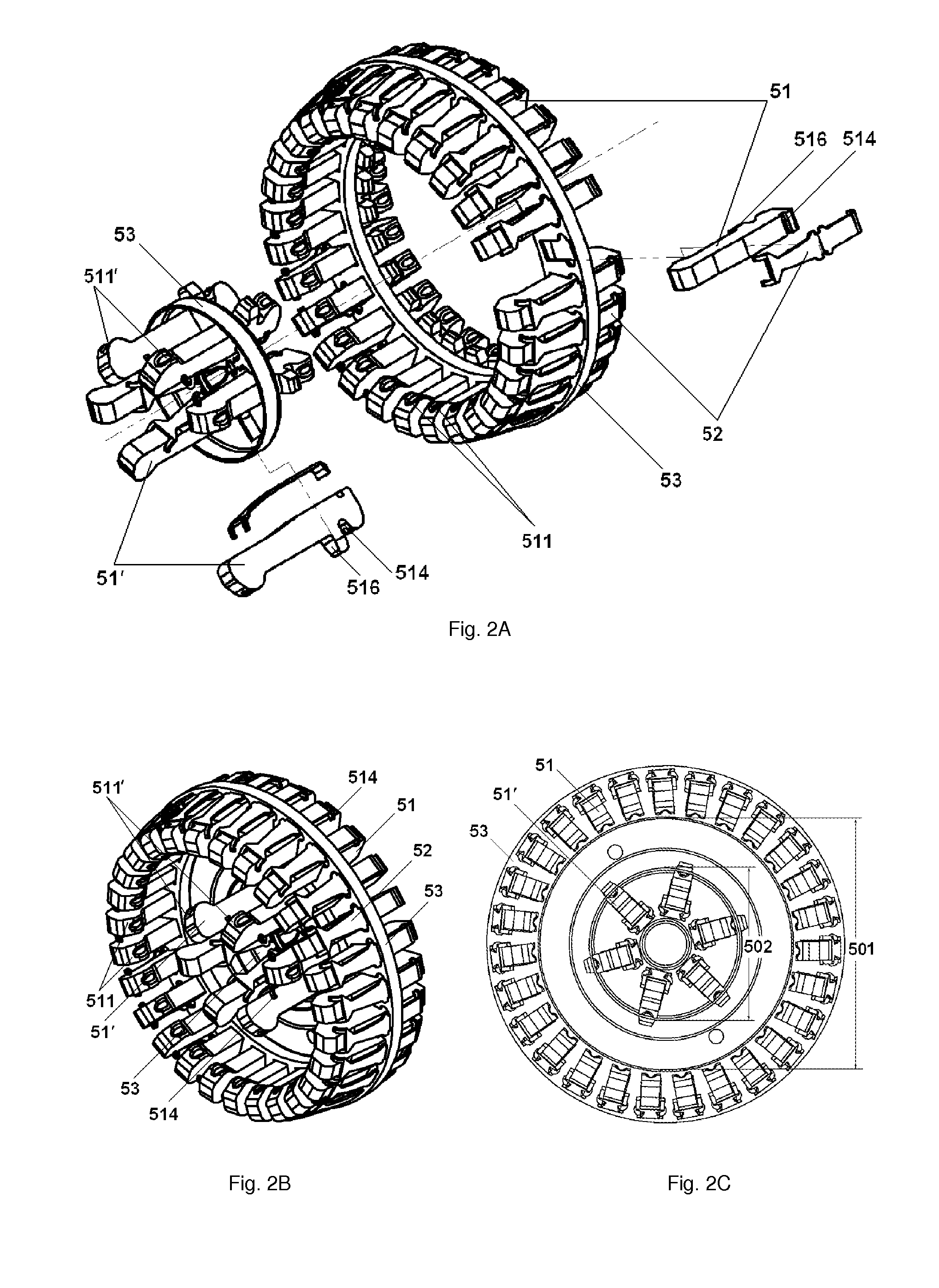
[0033]FIG. 2 shows the structure of the tulip contact according to one preferred embodiment of the present invention; in which FIG. 2A is the exploded view of the tulip contact, FIG. 2B is a perspective view of the tulip contact. The tulip contact for switching device comprises a plurality of outer contact fingers 51 and inner contact fingers 51′. Each of the contact fingers comprises a groove 514 and a holding block 516. As shown in FIG. 2 and FIG. 3, a leaf spring 522 is embedded in the grooves 514 of each of the outer contact fingers 51 and fixes the outer contact fingers 51 on a disk 53. The outer contact fingers 51 form a circular shape and are adapted to make the contact surface 511 of each of these fingers contact with the outer surface 41 of fixed contact 4. As shown in FIG. 2C and FIG. 3, the internal diameter 501 of the circle formed by the outer contact fingers...


PUM


Abstract

A tulip contact comprises a plurality of outer contact fingers and inner contact fingers. The outer contact fingers forming a shape of the outer surface of fixed contact in order to make the contact surface of each of these fingers contact with the outer surface of fixed contact. The inner contact fingers forming a shape of the inner surface of fixed contact in order to make the contact surface of each of these fingers contact with the inner surface of fixed contact. Each said contact finger comprises a first contact bulge for contacting with the surfaces of the fixed contact, and a second contact bulge for contacting with the bushing. And each said contact bulge comprises a contact slot on its surface. The first contact bulges of the outer contact fingers are not at the same cross section with the first contact bulges of the inner contact fingers.

Description

RELATED APPLICATION[0001]This application is a national filing of PCT application Serial No. PCT / CN2009 / 073212, filed Aug. 12, 2009.FIELD OF THE INVENTION[0002]This invention relates generally to the field of power products and power system, and more particularly to a contact mechanism and electrical contact system for switching device.BACKGROUND OF THE INVENTION[0003]Tulip contact is generally used in middle and / or high voltage switching devices. The contact fingers are essentially intended for rated electrical current disconnection operation and current transmission by providing a contact finger-trap which is connected to a mating contact.[0004]U.S. Pat. No. 4,072,392A discloses a spring wire formed tulip contact which comprises cylindrical male contact 11 and female members 12, as shown in FIG. 1A. The female member 12 is formed by placing a number of spring wire fingers 13 around the outer circumference of a cylindrical stud member 14 in such a manner that the fingers 13 extend ...

Claims


Application Information

Patent Timeline
Patent Type & Authority Patents(United States)
IPC IPC(8): H01R13/642H01R13/64
CPCH01H1/62H01H1/385
Inventor TU, ZHANWEIZHU, KUIKUILV, YURONG
Owner ABB (SCHWEIZ) AG
Why Eureka
Try Eureka