
Advance manufacturing monitoring and diagnostic tool

a technology for manufacturing monitoring and diagnostic tools, applied in the direction of instruments, nuclear elements, semiconductor operation lifetime testing, etc., can solve problems such as system or component failure, and achieve the effects of saving money and time, facilitating employability, and enhancing the breadth of information

Active Publication Date: 2014-02-04
NOKOMIS
View PDF124 Cites 30 Cited by
  • Summary
  • Abstract
  • Description
  • Claims
  • Application Information

AI Technical Summary

Benefits of technology

Enables remote, automated monitoring and diagnosis of electrical devices, reducing maintenance costs and downtime by providing detailed health assessments and predictive insights into component degradation, allowing for proactive maintenance and improved troubleshooting capabilities.

Problems solved by technology

All of these systems make use of electricity and exhibit wear that degrades their performance over time and can lead to system or component failure.

Method used


Image

  • Advance manufacturing monitoring and diagnostic tool
  • Advance manufacturing monitoring and diagnostic tool
  • Advance manufacturing monitoring and diagnostic tool

Examples


Embodiment Construction

, particularly, when such description is taken in conjunction with the attached drawing figures and with the appended claims.

BRIEF DESCRIPTION OF THE DRAWINGS

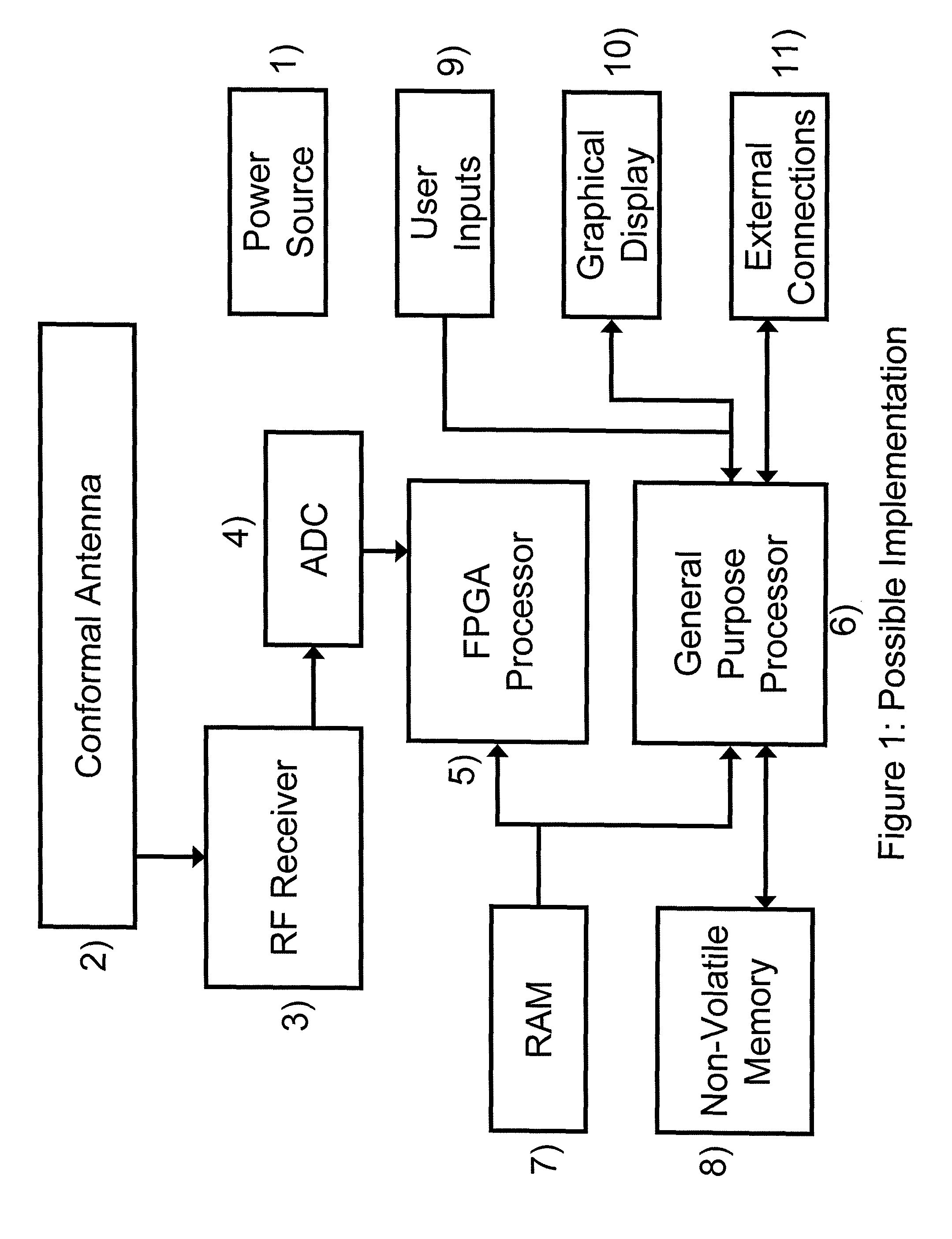
[0079]FIG. 1 is a diagram of an example embodiment of the components utilized in the present invention.

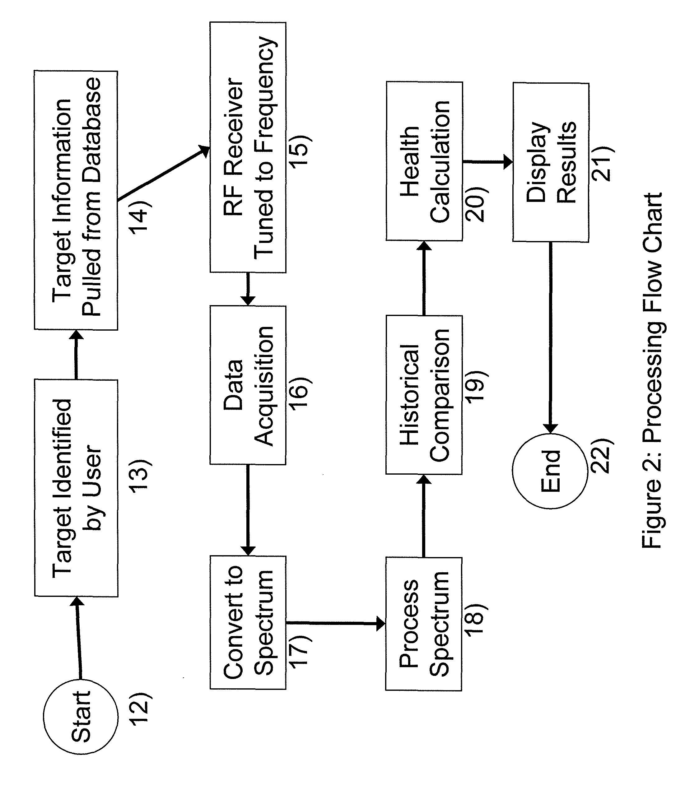
[0080]FIG. 2 is a diagram of an example embodiment of the functionality of the present invention.

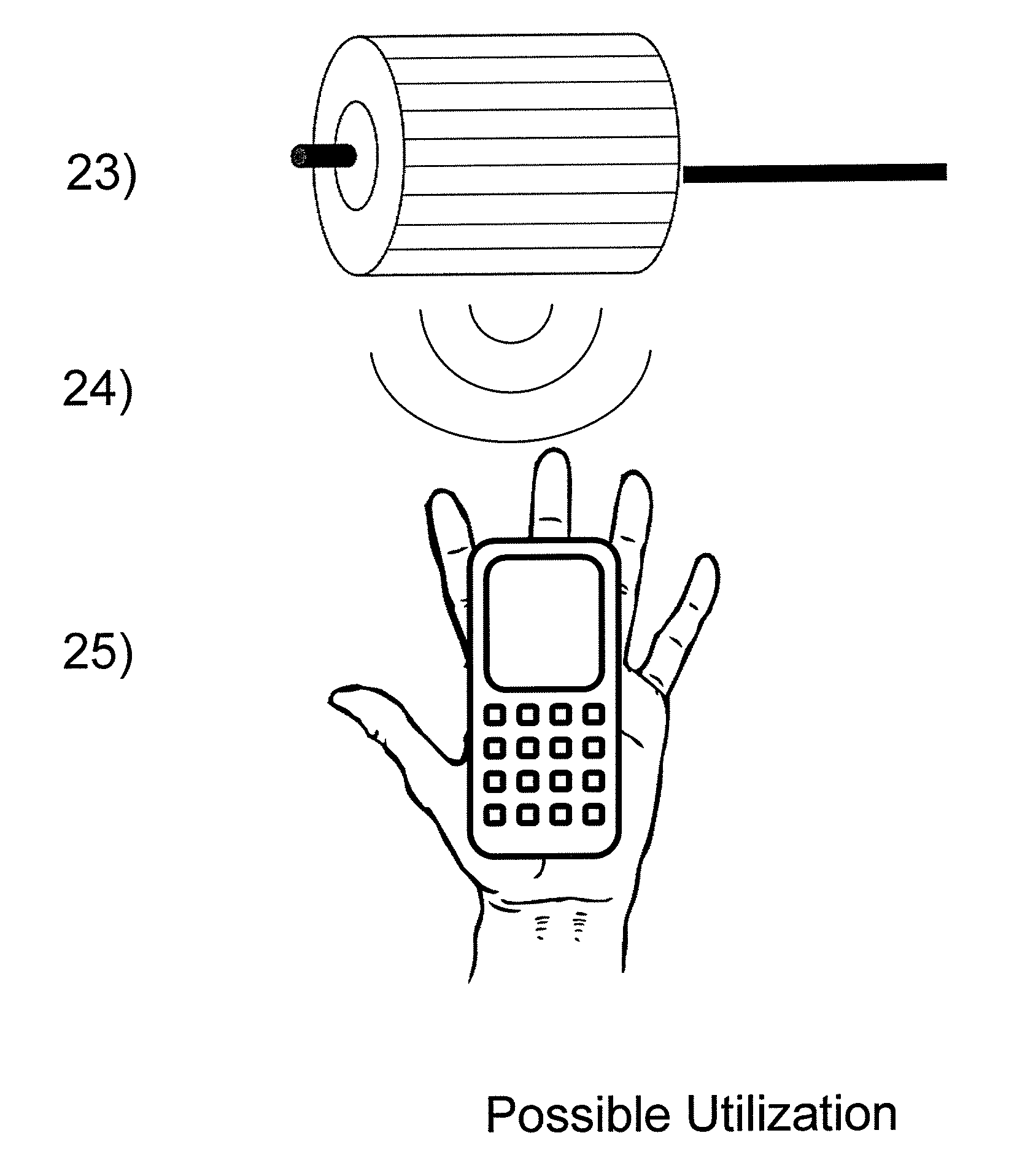
[0081]FIG. 3 is a diagram of an example embodiment of the invention is use.

BRIEF DESCRIPTION OF A PRESENTLY PREFERRED AND VARIOUS ALTERNATIVE EMBODIMENTS OF THE INVENTION

[0082]Prior to proceeding to the more detailed description of the present invention it should be noted that, for the sake of clarity and understanding, identical components which have identical functions have been identified with identical reference numerals throughout the several views illustrated in the drawing figures.

[0083]Reference is now made, more particularly, to FIG. 1 of the drawings which provides a diagram of the components that could be utilized in the...


PUM

PropertyMeasurementUnit
electromagnetic frequencyaaaaaaaaaa
electromagnetic energyaaaaaaaaaa
electromagnetic emission measurementaaaaaaaaaa

Abstract

The current invention relates to a monitoring and analysis device and a method for monitoring and analysis that utilizes the unintended electromagnetic emissions of electrically powered systems. The present invention monitors electrical devices by taking detailed measurements of the electromagnetic fields emitted by any component or system utilizing electricity. The measurements will be analyzed to both record a baseline score for future measurements and to be used in detailed analysis to determine the status of the analyzed system or component.

Description

CROSS REFERENCE TO RELATED APPLICATION[0001]This patent application is related to and claims priority from U.S. Provisional Patent Application Ser. No. 61 / 199,650 filed Nov. 19, 2008 and is herein incorporated by reference.FIELD OF THE INVENTION[0002]The present invention relates, in general, to the monitoring and diagnosis of electrical devices by measuring electromagnetic emissions and, more particularly, this invention relates to a monitoring and analysis device and a method for monitoring and analysis that utilizes the unintended electromagnetic emissions of electrically powered systems.BACKGROUND OF THE INVENTION[0003]Many of the concepts of the present invention are outlined in U.S. Pat. No. 7,515,094 and U.S. patent application Ser. No. 12 / 422,646 and are herein incorporated by reference.[0004]The current invention relates to the field of electromagnetic emissions of electrically powered systems. Specifically it relates to systems or components of systems that require electri...

Claims


Application Information

Patent Timeline
Patent Type & Authority Patents(United States)
IPC IPC(8): G21C17/00G01R31/265G01R31/302G01R31/02G01R31/04G01R31/00G01S13/00G01N37/00G01S7/40
CPCG01R29/0871G01S7/41G01R29/0892G01R31/006G01R31/008G01R31/265G01R31/2829G01R31/2894G01R31/315G01R31/3278G01R31/34G01R35/00G01R31/62G01R31/72G01R31/26G01R31/2642G01R31/2851G01R31/302G01R31/31703
Inventor PAULY, GERALD WILLIAMKELLER, III, WALTER JOHN
Owner NOKOMIS
Learn More