
Method and a device for overvoltage protection, and an electric system with such a device

a technology of overvoltage protection and device, which is applied in the direction of power conversion systems, electrical devices, and arrangements responsive to excess voltage, can solve the problems of increasing the wear of surge arresters, and achieve the effect of improving overvoltage protection

Active Publication Date: 2014-02-04
HITACHI ENERGY LTD
View PDF16 Cites 9 Cited by
  • Summary
  • Abstract
  • Description
  • Claims
  • Application Information

AI Technical Summary

Benefits of technology

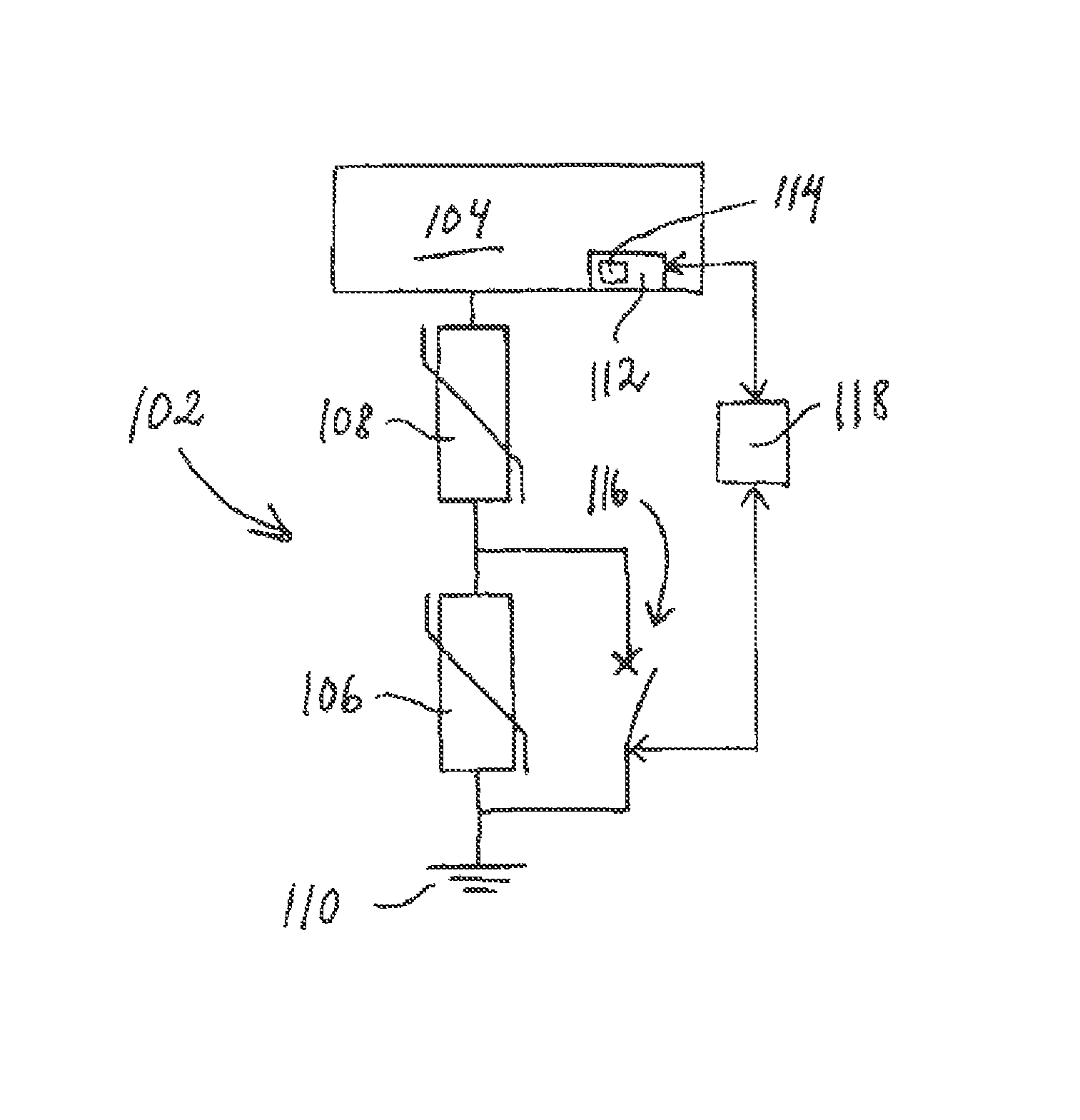
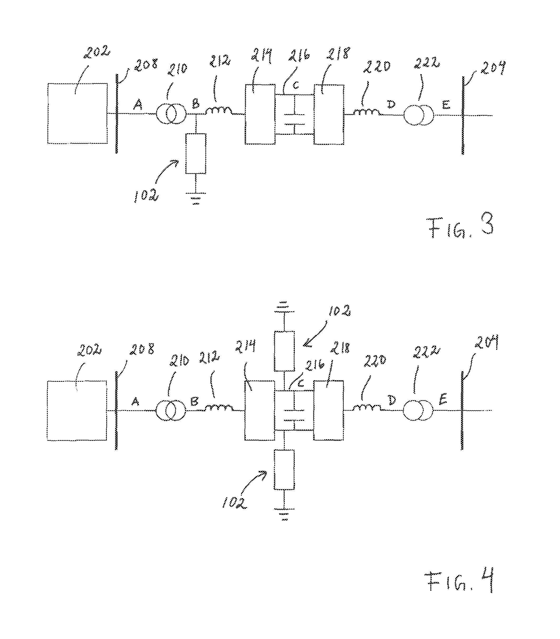
The present invention is a device that helps protect electric systems from overvoltages, which can occur when there is a fault in the system. The device can detect overvoltages and short circuit a surge arrester in parallel, which helps to absorb the energy in the system and reduce the overvoltages. This improves the efficiency of overvoltage protection for the electric system. The device can be placed at various points in the system and, when used in a wind farm, it doesn't have to stop the wind turbines from operating when there is a fault. Overall, the method of using the device can help to keep electric systems safe and secure.

Problems solved by technology

This increases the wear on the surge arrester.

Method used


Image

  • Method and a device for overvoltage protection, and an electric system with such a device
  • Method and a device for overvoltage protection, and an electric system with such a device
  • Method and a device for overvoltage protection, and an electric system with such a device

Examples


first embodiment

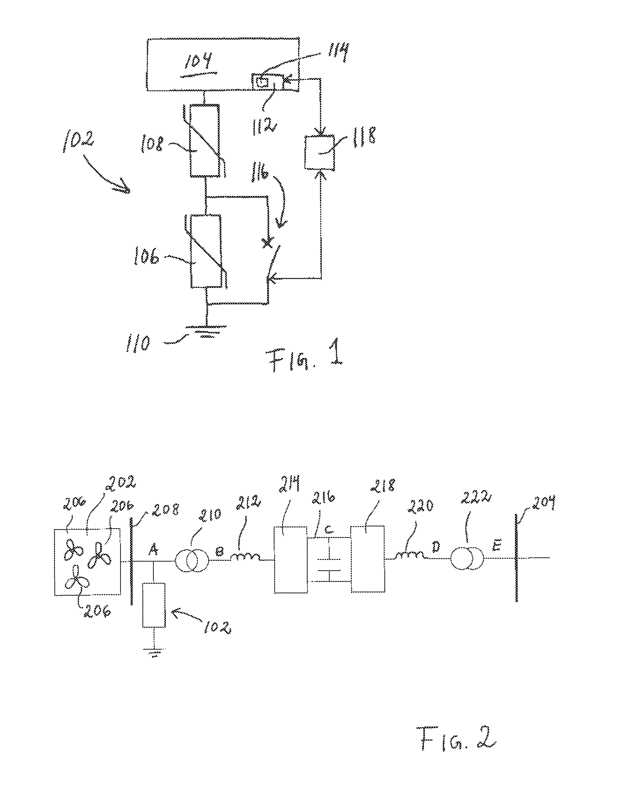
[0041]FIG. 2 illustrates the electric system according to the present invention which is adapted to be subjected to voltages, which electric system comprises a wind farm 202 connected to an AC grid 204, as it is known in prior art. The wind farm 202, which can be located offshore, includes a plurality of wind turbines 206 and is coupled to a local AC bus 208, the local AC bus 208 being connected via a first transformer 210 and a first inductor / reactor 212 to a first VSC-converter 214. The first VSC-converter 214 is connected via a DC link 216 to a second VSC-converter 218 and the VSC-converter 218 is connected via a second inductor / reactor 220 and a second transformer 222 to the AC grid 204, which can be located onshore. The first VSC-converter 214 converts AC to DC, and the second VSC-converter 218 converts DC to AC. The VSC-converters 214, 218 may be of conventional type known to the skilled person, and the function of the VSC-converters 214, 218 is well known to the person skille...

fourth embodiment

[0047]FIG. 5 illustrates the electric system according to the present invention which is adapted to be subjected to voltages. The electric system of FIG. 5 corresponds to the electric system as illustrated in FIG. 2, but includes two line-commutated converters (LCC) 502, 504 instead of the two VSC-converters 214, 218, and the two inductors / reactors 212, 220 are excluded. In the electric system of FIG. 5, the device 102 as disclosed in FIG. 1 is connected to the electric system on the rectifier side at the position A between the local AC bus 208 and the first transformer 210. The LCC-converters 502, 204 may be of conventional type known to the skilled person, and the function of the LCC-converters 502, 204 is well known to the person skilled in the art and is not more closely described here.

[0048]FIG. 6 illustrates a fifth embodiment of the electric system according to the present invention which corresponds to the electric system as illustrated in FIG. 5, but where the electric syst...


PUM


Abstract

A method and device for protecting an electric system against overvoltage occurrences, the electric system being adapted to be subjected to voltages. The device includes a plurality of surge arresters and a detector configured to detect overvoltage occurrences in the electric system. The surge arresters are connected in series, the plurality of surge arresters including a first surge arrester which is connectable to ground and a second surge arrester which is connectable to the electric system which is to be protected. The device includes a switch connected in parallel with at least one surge arrester of the plurality of surge arresters, and the switch is adapted to be open when no overvoltage occurrence is detected and adapted to close upon overvoltage occurrence detection and short-circuit the surge arrester with which it is connected in parallel. An electric system includes at least one such device.

Description

TECHNICAL FIELD[0001]The present invention relates to a method for protecting an electric system against overvoltage occurrences, the electric system being adapted to be subjected to voltages. Further, the present invention relates to a device for protecting an electric system against overvoltage occurrences, the electric system being adapted to be subjected to voltages, which device comprises a plurality of surge arresters and comprises detection means for detecting overvoltage occurrences in the electric system. The present invention also relates to an electric system comprising a device as mentioned above.BACKGROUND OF THE INVENTION[0002]There is a need for improved overvoltage protection for electric systems, for example electric systems including VSC-converters (VSC=Voltage Source is Converter), electric systems including line-commutated converters, and / or electric systems including power transmission lines, for example, High Voltage Direct Current (HVDC) transmission systems.[...

Claims


Application Information

Patent Timeline
Patent Type & Authority Patents(United States)
IPC IPC(8): H02H3/22
CPCH02M1/32
Inventor NUNES, JOSEKARLSSON, JONAS
Owner HITACHI ENERGY LTD
Learn More