Optical image measuring device and control method thereof

a technology of optical image and measuring device, which is applied in the field of optical image measuring device, can solve the problems of affecting reducing the efficiency of collection, so as to achieve the effect of efficient collection

Active Publication Date: 2014-02-11
KK TOPCON
View PDF14 Cites 0 Cited by
  • Summary
  • Abstract
  • Description
  • Claims
  • Application Information

AI Technical Summary

Benefits of technology

[0027]According to the present invention, even if an optical system that can condense a signal light to the first depth zone is obtained, by inserting a depth zone switching lens and switching light path of the reference light to an optical path length that corresponds to a second depth zone by a switching part, the signal light reflected by the second depth zone that is different from the first depth zone can be efficiently collected. Therefore, even with an optical image measuring device that has an optical system that mainly measures the first depth zone, detailed information of each depth position of the second depth zone can be collected and this entire second depth zone can be vividly photographed.
[0028]For example, when the first depth zone is considered to be a fundus oculi and the second depth zone is considered to be an anterior segment, this optical image measuring device can obtain not only vivid OCT images of the fundus oculi but also vivid OCT images of the anterior segment by inserting the depth zone switching lens. In OCT images of the anterior segment that are obtained by this optical image measuring device, not only the surface of a cornea but also each layer position of an anterior segment is vividly shown.

Problems solved by technology

Therefore, although a variety of organism information can be obtained as a vivid tomographic image from OCT images of the fundus oculi Ef shown in FIG. 14B, according to OCT images of the anterior segment Ea shown in FIG. 14A, because the corneal reflection light from the vertex Ec is of high intensity, it can be distinguished, but because distinguishing the other part such as a posterior surface of the cornea or crystalline lens is difficult, this organism information is almost impossible to obtain.
However, with this photographing method, because a total of two adjustments of the distance between the objective lens 113 and the corneal vertex Ec must be performed, the examination time becomes long and both the examiners and subject bear a large burden.

Method used


Image

  • Optical image measuring device and control method thereof
  • Optical image measuring device and control method thereof
  • Optical image measuring device and control method thereof

Examples


Embodiment Construction

[0171]An example of an embodiment of an optical image measuring device according to the present invention will be described in detail with reference to the drawings.

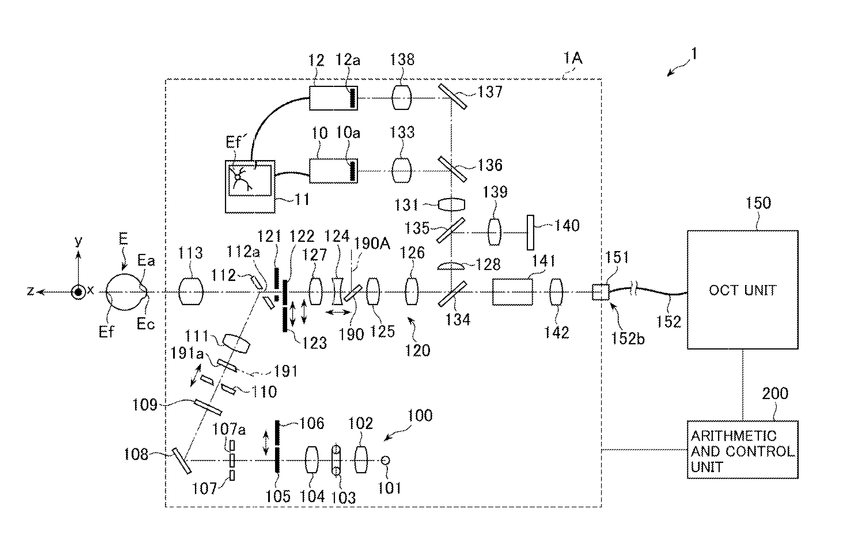
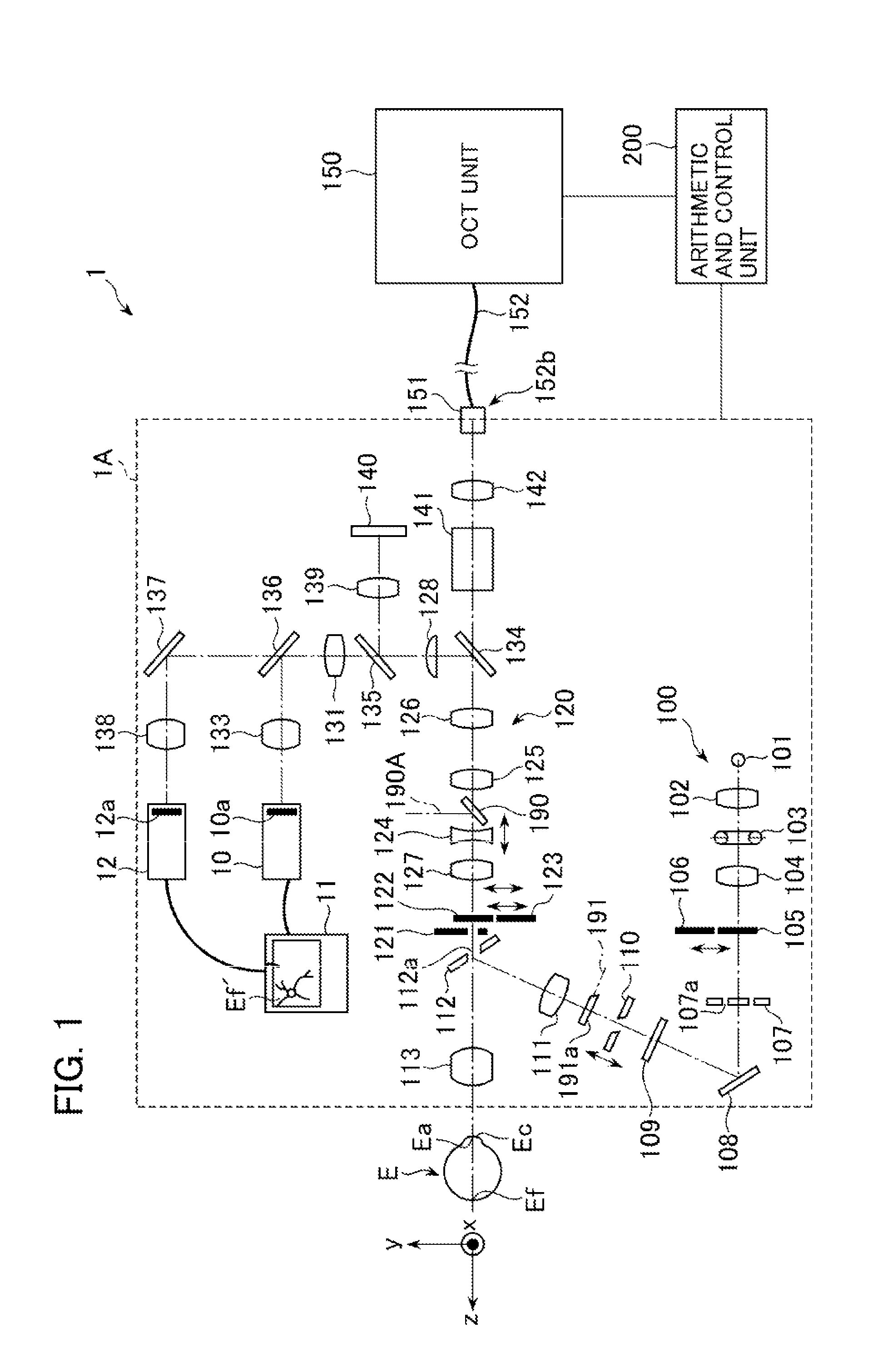
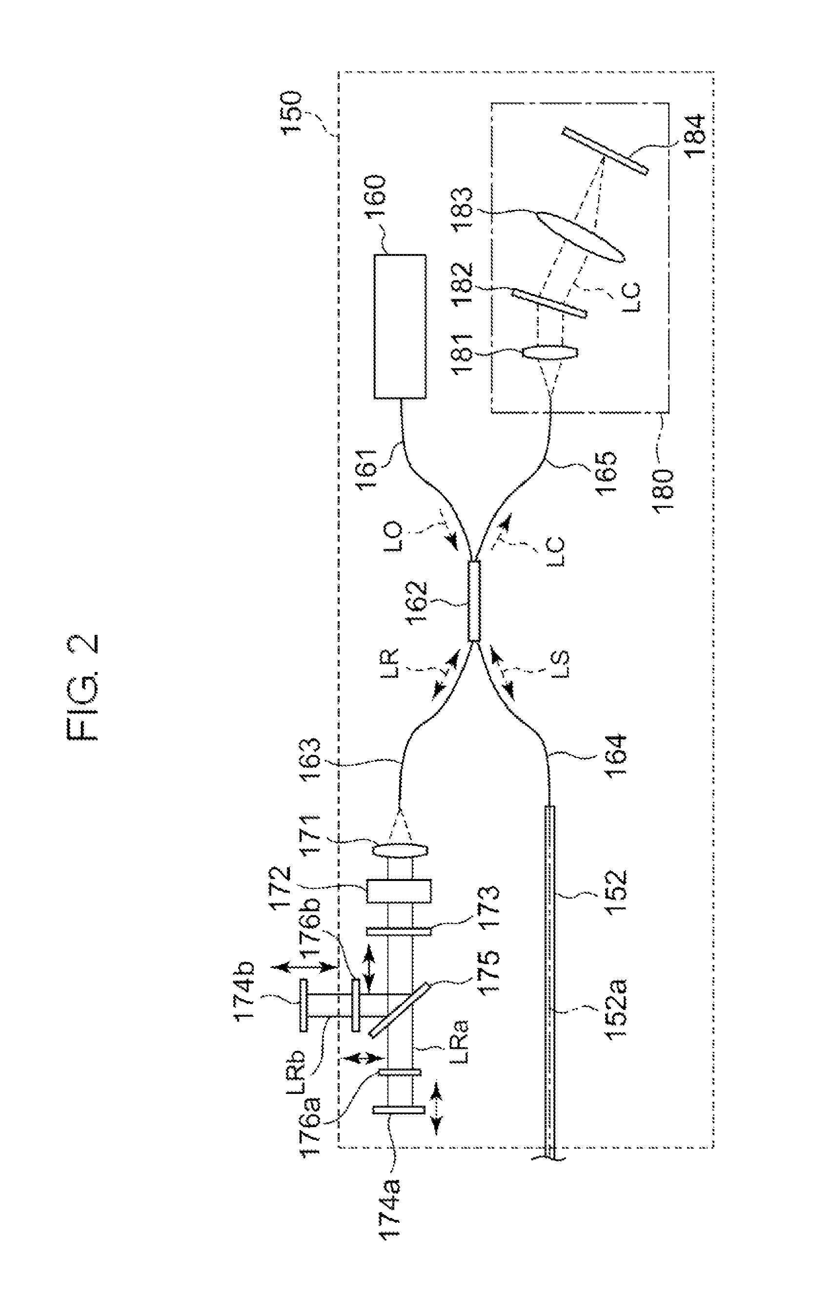
[0172]FIG. 1 is a figure showing a configuration of an optical image measuring device 1 according to the present embodiment. FIG. 2 is a figure showing an optical system of an OCT unit 150 in the optical image measuring device 1.

[0173]The optical image measuring device 1 according to the present embodiment is used in the ophthalmologic field to acquire an OCT image of an eye E. The OCT image is a tomographic image or a three-dimensional image of the eye E. A like effect can be obtained by a like configuration also at the time of acquisition of an OCT image of a measured object other than a living eye.

[0174]The optical image measuring device 1 includes a configuration to which a Fourier-Domain-type method is applied. To be specific, in this embodiment, the optical image measuring device 1 is provided with almost the same ...


PUM


Abstract

A low-coherence light is split into a signal light and a reference light. The optical path length of the reference light is switched to optical path lengths that correspond to a first depth zone and a second depth zone. When forming a tomographic image of the second depth zone, in an optical system that condenses the signal light to the first depth zone when a measured object and an objective lens are located at a predetermined working distance, while being positioned at the working distance, a depth zone switching lens that transitions the depth at which the signal light is condensed to the second depth zone is inserted.

Description

TECHNICAL FIELD[0001]The present invention relates to an optical image measuring device configured to form images that show the surface morphology and internal morphology of measured objects by using a light beam, and a control method thereof.BACKGROUND ART[0002]In recent years, an optical image measuring technique of forming images that show the surface morphology and internal morphology of measured objects by using a light beam from a laser light source or the like has attracted attention. Unlike an X-ray CT apparatus, the optical image measuring technique is noninvasive to human bodies, and is therefore expected to be utilized more particularly in the medical field and biological field.[0003]Japanese Unexamined Patent Application Publication No. Hei 11-325849 (Patent Document 1) discloses a device to which the optical image measuring technique is applied. This device has such a configuration that: a measuring arm scans an object by a rotary deflection mirror (a Galvano mirror); a...

Claims


Application Information

Patent Timeline
Patent Type & Authority Patents(United States)
IPC IPC(8): A61B3/14A61B3/00
CPCA61B3/14A61B3/102A61B3/117G01B9/02044G01B9/02091G01B9/02063G01B9/02029A61B3/12G01B9/02028
Inventor HAYASHI, TAKEFUMI
Owner KK TOPCON
Why Eureka
Try Eureka