Implant and system for predicting decompensation

a technology implants, applied in the field of compensating medical devices with implants, can solve the problems of high dependence, and low specificity of prediction devices based on this approach

Active Publication Date: 2014-02-18
BIOTRONIK SE & CO KG
View PDF12 Cites 8 Cited by
  • Summary
  • Abstract
  • Description
  • Claims
  • Application Information

AI Technical Summary

Benefits of technology

[0015]It is advantageous that the attenuation coefficient of water is several times lower than the attenuation coefficient of air. Thus, rising water content in the pulmonary tissue directly and considerably affects the attenuation coefficient. It is furthermore advantageous that the attenuation coefficient is substantially independent from the electrolyte balance of the patient as well as the packed cell volume. In this way, a received acoustic signal clearly differs from any interfering signals that may be present. The implant therefore achieves a prediction signal having particularly high specificity.
[0065]The invention also encompasses systems which incorporate the implant, such as an implant as described above, a patient device communicating with the implant, and a processor station in communication with the patient device. The implant of the present invention can thus also be incorporated in a home monitoring system. For example, the implant can include an additional transceiver which is designed to transmit the determined attenuation value (and / or the reduction values, and / or the amplitude values, and / or the prediction signal) to the patient device associated with the patient. The patient device, in turn, can transmit the determined attenuation value (and / or the reduction values, and / or the amplitude values, and / or the prediction signal) to the processor station communicating with the patient device. In this way, the implant also benefits from the many advantages that a home monitoring system offers. For example, the patient device and / or the processor station may assume part of the signal processing operation, transmit a certain threshold value to the implant, or store and compare evaluation data of a plurality of implants.

Problems solved by technology

The disadvantage here is that the electrical conductivity of the blood, which is subject to natural fluctuations, has considerable influence on the impedance measurement, so that prediction devices based on this approach have a comparatively low specificity.
Unfortunately, this method suffers from the disadvantage that the sound velocity is dependent not only on the rate of fluid in the pulmonary tissue, but also highly dependent on the breathing cycle, i.e., the fluctuation of the air volume in the lungs.
In order to be able to detect fluid buildup in the pulmonary tissue and an associated change in the travel time, the signal processor in the described prediction device must have a resolution of approximately 100 ns, which is difficult to achieve without significant complexity.
Very small changes in the distances, such as those caused by a natural change in the size of the lungs or by variably deep breathing processes, can result in travel time changes, which can be mistaken for a change in the sound velocity and thereby possibly fluid buildup in the pulmonary tissue.
Thus, a prediction device of this type tends to exhibit low specificity, particularly after an extended idle time during which component distance changes tend to occur.
This disadvantage, as well as the need for a complex signal processing system, decreases the suitability of the acoustic method for implementation in implantable medical devices.

Method used


Image

  • Implant and system for predicting decompensation
  • Implant and system for predicting decompensation
  • Implant and system for predicting decompensation

Examples


Embodiment Construction

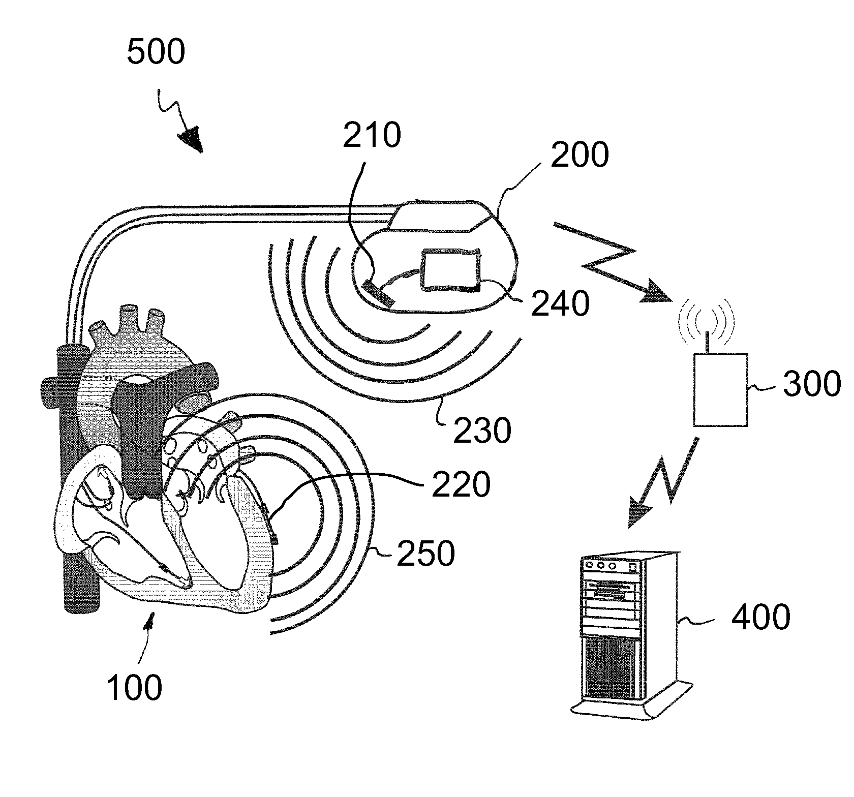
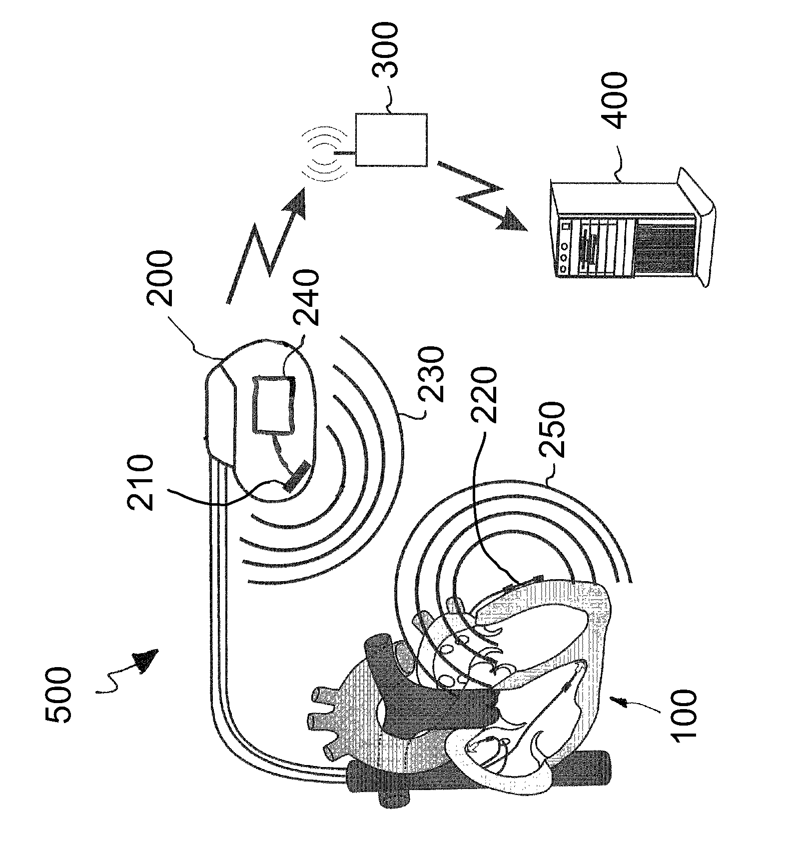
[0068]Referring to FIG. 1, the system 500 comprises a version 200 of the implant, a patient device 300, and a processor station 400. The implant 200 is used to predict decompensation of the heart 100 and is disposed in the thorax of the patient. The implant 200 comprises a first acoustic transducer 210 and a second acoustic transducer 220, which are matched to each other. The first acoustic transducer 210 is disposed in the housing of the implant. The second acoustic transducer 220 is disposed outside of the housing of the implant 200.

[0069]In the version illustrated in FIG. 1, the first acoustic transducer 210 is designed as a transmitting and receiving transducer and the second acoustic transducer 220 is designed as a reflector. The second acoustic transducer 220 is disposed in the vicinity of the heart 100, for example on an ICD electrode located there. In order to determine an attenuation value that is dependent on the acoustic attenuation coefficient present between the two aco...


PUM


Abstract

An implant predicts decompensation of a patient's heart based on an acoustic pressure measurement. The implant includes first and second acoustic transducers, which are matched to each other and which rest in / on the patient's thorax. The first acoustic transducer emits an acoustic signal which has at least one first signal portion having a first frequency. The second acoustic transducer is designed to receive and re-emit the emitted acoustic signal, or to reflect it, such that the first acoustic transducer receives the emitted acoustic signal. A signal processing unit communicates with at least one of the two acoustic transducers and determines an attenuation value as a function of the attenuation of the received acoustic signal versus the originally emitted acoustic signal, and provides a prediction signal as a function of a comparison of the attenuation value to a threshold value, wherein the prediction signal indicates the development of decompensation.

Description

CROSS-REFERENCE TO RELATED APPLICATIONS[0001]This application claims priority under 35 U.S.C. §119(e) to U.S. Provisional Patent Application 61 / 371,177 filed Aug. 6, 2010, the entirety of which is incorporated by reference herein.FIELD OF THE INVENTION[0002]The invention generally relates to the field of implantable medical devices for predicting cardiovascular abnormalities. More specifically, the invention relates to a system for predicting decompensation, including an implant for predicting decompensation of a patient's heart based on a measurement of acoustic tissue properties.BACKGROUND OF THE INVENTION[0003]Devices for predicting cardiovascular abnormalities are known, and are often integrated into (or connected to) an implanted cardiac pacemaker or cardioverter / defibrillator. It is desirable to design these prediction devices such that they predict a dysfunction of the cardiovascular system well in advance of the dysfunction, and with high specificity.[0004]Implants for predi...

Claims


Application Information

Patent Timeline
Patent Type & Authority Patents(United States)
IPC IPC(8): A61B8/00
CPCA61N1/3956A61N1/3704A61B8/08A61N1/3627A61B8/12A61N1/3925A61B8/4477A61B8/5223G16H50/30
Inventor SKERL, OLAFLIPPERT, MICHAEL
Owner BIOTRONIK SE & CO KG
Why Eureka
Try Eureka