
Offshore hydroelectric turbine assembly and method

a hydroelectric turbine and hydroelectric technology, applied in the direction of electric generator control, liquid fuel engines, machines/engines, etc., can solve the problems of criticized wave power, kinetic energy sources remain virtually untapped, and pose significant risks to ship and recreational watercraft traffic entering, so as to maximize turbine power and minimize yaw

Inactive Publication Date: 2014-02-18
ROONEY THOMAS
View PDF42 Cites 5 Cited by
  • Summary
  • Abstract
  • Description
  • Claims
  • Application Information

AI Technical Summary

Benefits of technology

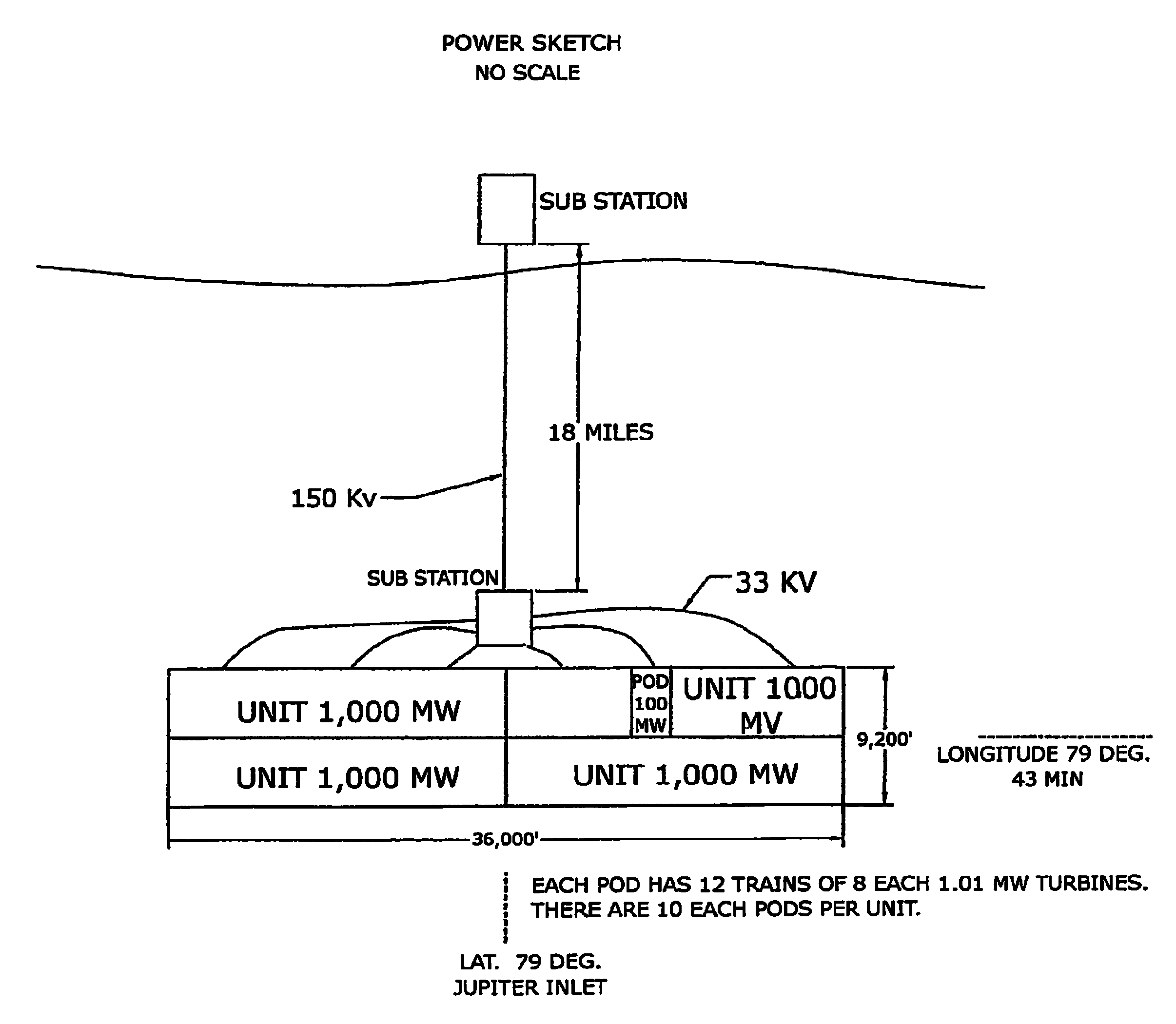
The patent describes a hydroelectric turbine assembly for use in ocean currents. The assembly includes a central control vessel that is anchored to the floor of the ocean and a plurality of turbine cables that connect to the control vessel. These cables form a rigid structure that helps stabilize the turbines in the ocean current. The turbines are positioned at an angle to maximize power and minimize yaw. The assembly also includes a means to control the buoyancy of the control vessel to maintain the same depth of the turbine assembly in the ocean. This ensures that the turbine array is positioned optimally for power production.

Problems solved by technology

Not all forms of hydroelectric power generation, such as the use of dams, are desirable due to environmental concerns.
Despite the ability to harness wave power as a second hydroelectric energy power generation scheme, many have criticized wave power because these systems obstruct the coastal shore.
However, all of these locations afford limited sources of deep water currents, while posing significant risks to ship and recreational watercraft traffic entering these large metropolitan waterways.
This source of kinetic energy remains virtually untapped-with limited plans for developing any technology to harness this alternative energy source.
This is largely attributed to the fact that while several means have been created to harvest ocean currents, few have been found to be viable.

Method used


Image

  • Offshore hydroelectric turbine assembly and method
  • Offshore hydroelectric turbine assembly and method
  • Offshore hydroelectric turbine assembly and method

Examples


Embodiment Construction

[0019]The present invention will now be described more fully hereinafter with reference to the accompanying drawings, in which preferred embodiments of the invention are shown. This invention may, however, be embodied in many different forms and should not be construed as limited to the embodiments set forth herein. Rather, these embodiments are provided so that this disclosure will be thorough and complete, and will fully convey the scope of the invention to those skilled in the art. Like numbers refer to like elements throughout.

Overall Components of the Turbine Assembly

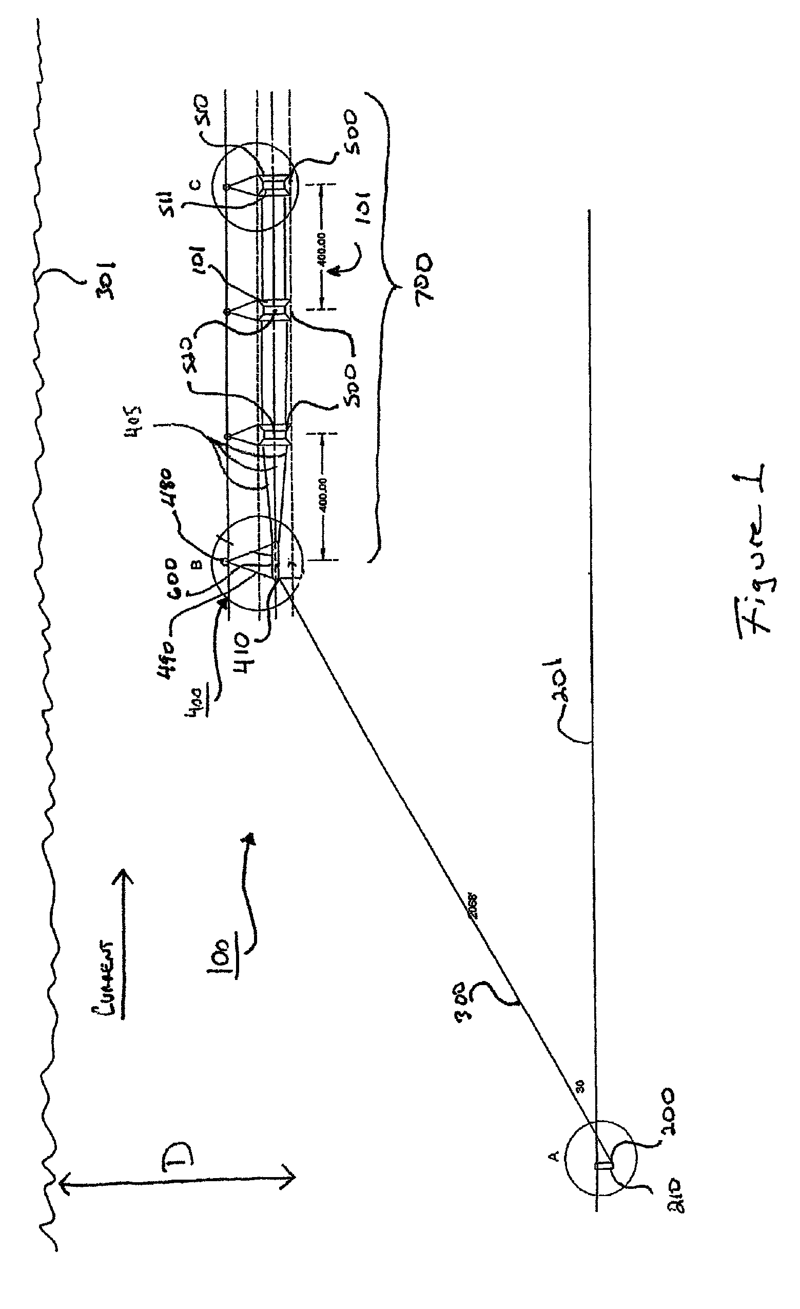
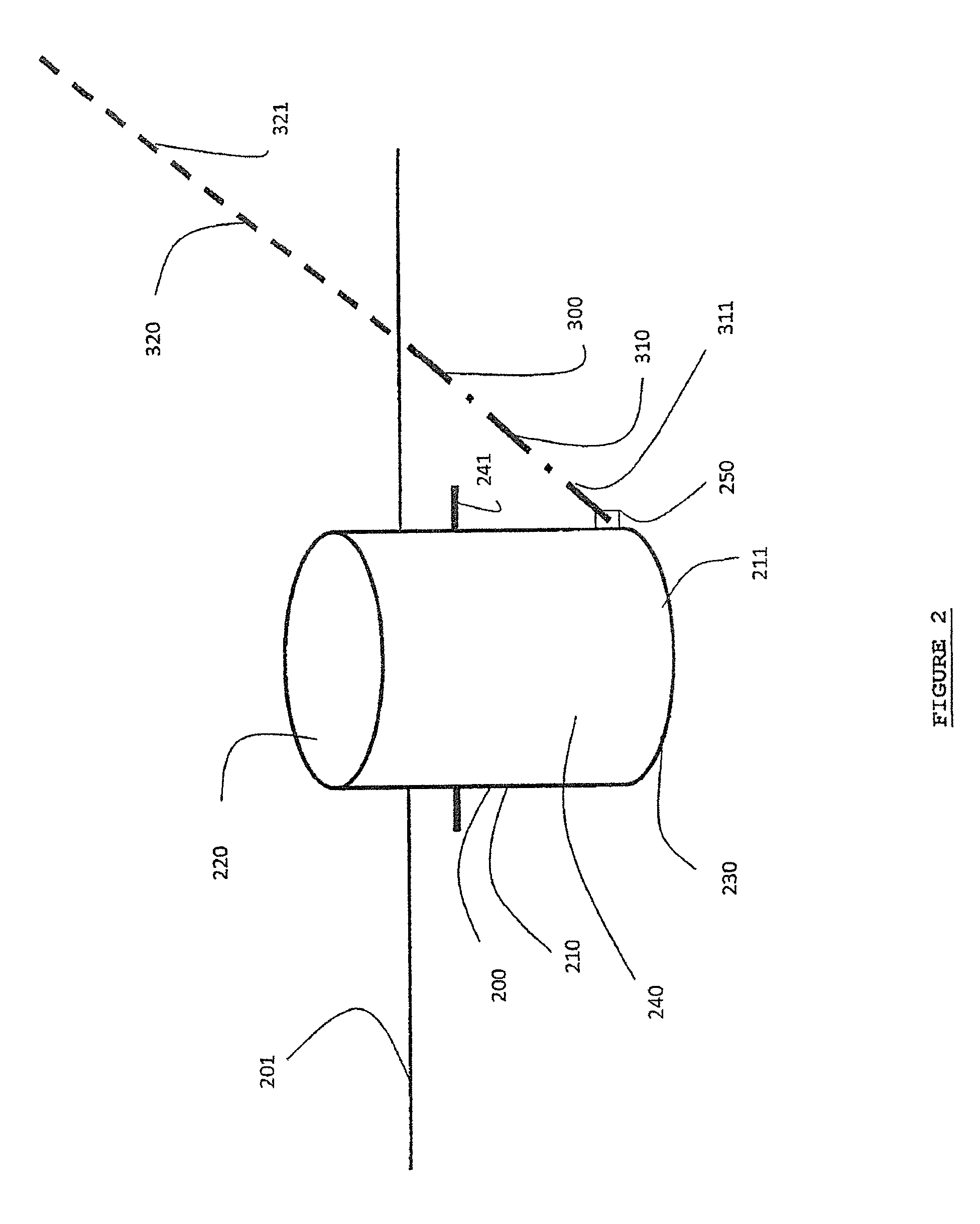
[0020]FIG. 1 illustrates, by way of example, the preferred components 101 of an assembly 100 used to harness the kinetic energy of deep water currents (which can be drawn from the ocean, rivers, or other waterways). As shown, the assembly 100 preferably includes an anchoring point 200, a mooring line 300, and a central control vessel 400 attached to the anchoring point 200 via the mooring line 300. A plurality of t...


PUM


Abstract

The invention is directed to a single moored offshore marine turbine assembly having a central control vessel which includes a main vessel tethered to a control buoy. The main vessel having a first cap, a corresponding second cap and a tubular shell positioned between both the first cap and second cap. The tubular shell contains one or more vertical partitions to assist in ballasting. The control buoy includes a compressor and an air conduit which forces air into the main vessel through a manifold. A hollow suction caisson affixes the central control vessel to the ocean floor. A taut line mooring secures the suction caisson to the main vessel. Electricity is generated via a turbine shroud assembly having a conical shroud and a hydro-turbine. By attaching a plurality of turbine shroud assemblies in series via cables, a horizontal turbine array is formed resulting in a simple, economical and safe layout.

Description

CROSS-REFERENCE TO RELATED APPLICATION[0001]This is a Continuation in Part Application of U.S. patent application Ser. No. 12 / 891,241 filed on Sep. 27, 2010 now U.S. Pat. No. 8,558,403 entitled “Single Moored Offshore Horizontal Turbine Train,” which is incorporated by reference herein.FIELD OF THE INVENTION[0002]The invention is directed to a tethered array of hydroelectric turbines and related methods designed to harness kinetic energy from water currents.BACKGROUND OF THE INVENTION[0003]With the continued rise in fossil fuel costs and associated risks in acquiring such fuels, a large number of alternative energy solutions have recently risen in popularity. Such alternative energy solutions not only decrease dependence upon foreign countries to supply energy to the United States, but also serve to decrease the carbon footprint and reverse the effects of global warming. Additionally, such sustainable alternative solutions reduce the price of energy in the long-term.[0004]Hydroelect...

Claims


Application Information

Patent Timeline
Patent Type & Authority Patents(United States)
IPC IPC(8): F03B13/00H02P9/04F03B13/10
CPCY02E10/22F03B13/10F05B2250/232Y02E10/28F05B2240/40F05B2270/18F03B17/061F05B2240/13Y02E10/20Y02E10/30
Inventor ROONEY, THOMAS
Owner ROONEY THOMAS
Learn More