Heat exchanger for an electronic display

a technology of electronic display and heat exchanger, which is applied in the direction of lighting and heating apparatus, instruments, laminated elements, etc., can solve the problems of damage to the interior components of the display, insufficient in many climates, and large screen size of the display mark

Active Publication Date: 2014-02-18
MFG RESOURCES INT INC
View PDF55 Cites 80 Cited by
  • Summary
  • Abstract
  • Description
  • Claims
  • Application Information

AI Technical Summary

Problems solved by technology

By itself, this is not adequate in many climates, especially when radiative heat transfer from the sun through a display window becomes a major factor.
Furthermore, the market is demanding larger screen sizes for displays.
Also, when displays are used in outdoor environments the ambient air may contain contaminates (dust, dirt, pollen, water vapor, smoke, etc.) which, if ingested into the display for cooling the interior can cause damage to the interior components of the display.
Such temperature fluctuation adversely affects the electronic components in these devices; both performance and lifetime may be severely affected.

Method used


Image

  • Heat exchanger for an electronic display
  • Heat exchanger for an electronic display
  • Heat exchanger for an electronic display

Examples


Embodiment Construction

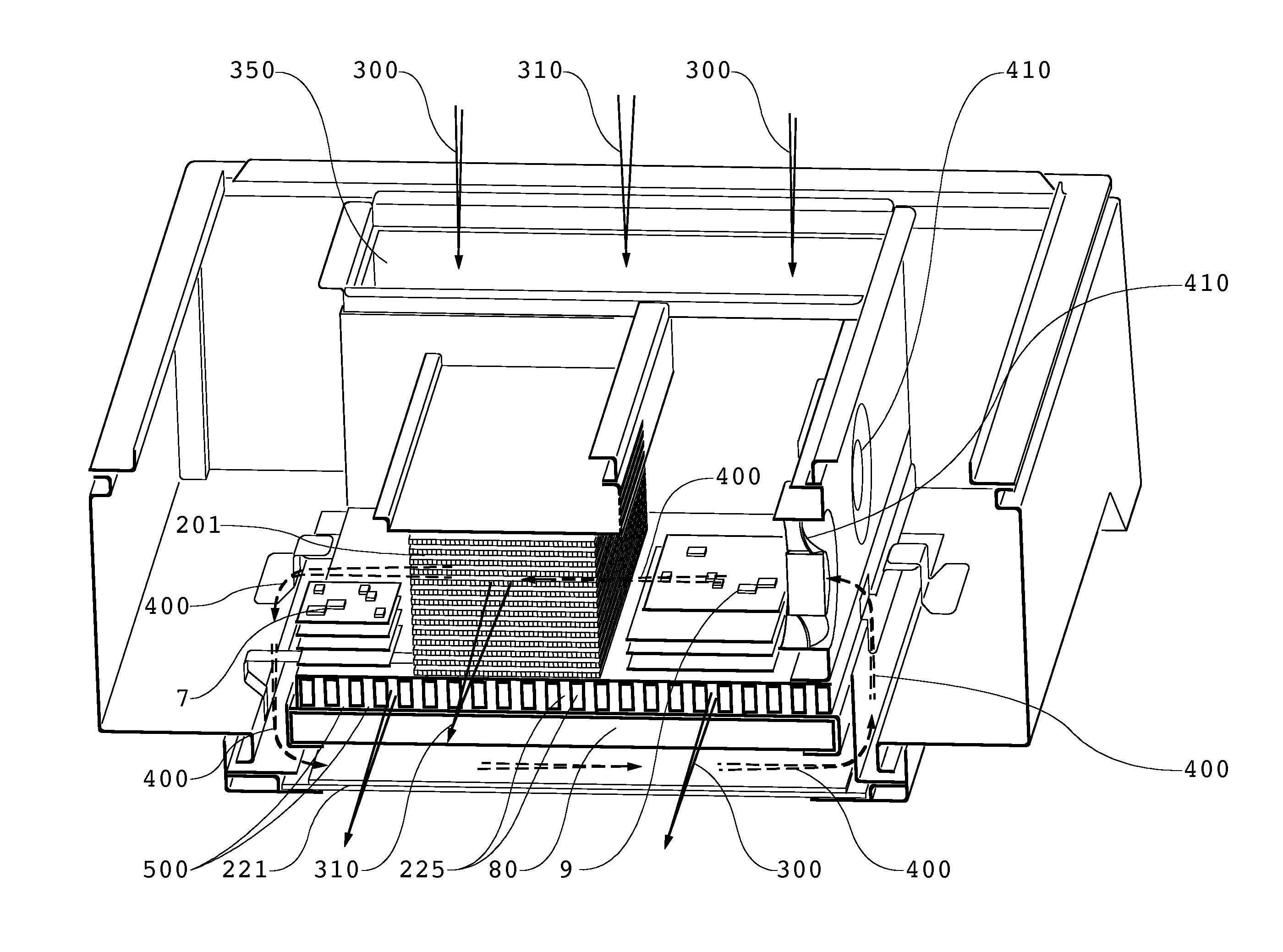
[0006]Exemplary embodiments may comprise two separate flow paths for gas through an electronic display. A first flow path may be a closed loop and a second flow path may be an open loop. The closed loop path travels across the front surface of the image assembly, continues to the rear of the display where it may enter a heat exchanger, finally returning to the front surface of the image assembly. The open loop path may draw ambient gas (ex. ambient air) through the rear of the display (sometimes through a heat exchanger, behind an image assembly, or both) and then exhausts it out of the display housing. A heat exchanger may be used to transfer heat from the circulating gas to the ambient gas. In alternative embodiments, the ambient gas may also be forced behind the image assembly (sometimes a backlight), in order to cool the image assembly and / or backlight assembly (if a backlight is necessary for the particular type of display being used). A cross-flow heat exchanger may be used in...


PUM

PropertyMeasurementUnit
poweraaaaaaaaaa
forceaaaaaaaaaa
transparentaaaaaaaaaa

Abstract

A cooling assembly for an electronic image assembly having an open and closed gaseous loop. A closed gaseous loop allows circulating gas to travel across the front surface of an image assembly and through a heat exchanger. An open loop allows ambient gas to pass through the heat exchanger and extract heat from the circulating gas. An optional additional open loop may be used to cool the back portion of the image assembly (optionally a backlight). Ribs may be placed within the optional additional open loop to facilitate the heat transfer to the ambient gas. The cooling assembly can be used with any type of electronic assembly for producing an image.

Description

CROSS-REFERENCE TO RELATED APPLICATIONS[0001]This application is a non-provisional of U.S. Application No. 61 / 138,736 filed Dec. 18, 2008 and is hereby incorporated by reference as if fully cited herein. This application is a continuation in part of U.S. application Ser. No. 12 / 411,925 filed Mar. 26, 2009, which is a non-provisional application of U.S. provisional application No. 61 / 039,454 filed Mar. 26, 2008 each of which are hereby incorporated by reference as if fully cited herein. This application is a continuation-in-part of U.S. application Ser. No. 12 / 556,029 filed Sep. 9, 2009, which is a non-provisional application of U.S. provisional application No. 61 / 095,615 filed Sep. 9, 2008 each of which are hereby incorporated by reference as if fully cited herein. This application is a continuation-in-part of U.S. application Ser. No. 12 / 234,307 filed Sep. 19, 2008, which is a non-provisional application of U.S. Application No. 61 / 033,064 filed Mar. 3, 2008, each of which are hereb...

Claims


Application Information

Patent Timeline
Patent Type & Authority Patents(United States)
IPC IPC(8): F24H3/02H05K7/20F28D15/00G02F1/1333
CPCF28F3/02F28D9/00G02F1/133385H05K7/20972H05K7/202H05K7/20136H05K7/20163
Inventor DUNN, WILLIAMHUBBARD, TIMOTHY
Owner MFG RESOURCES INT INC
Why Eureka
Try Eureka