
Liquid cooled metal thermal stack for high-power dies

a metal thermal stack and high-power die technology, applied in the direction of electrical apparatus contruction details, semiconductor/solid-state device details, lighting and heating apparatus, etc., can solve the problems of increasing the thermal fatigue applied, increasing the cost of the component, and incorporating heat sinks into electrical components, so as to reduce the thermal fatigue and reduce the thermal fatigue. , the effect of easy conductivity of heat energy

Inactive Publication Date: 2006-04-04
VISTEON GLOBAL TECH INC
View PDF6 Cites 93 Cited by
  • Summary
  • Abstract
  • Description
  • Claims
  • Application Information

AI Technical Summary

Benefits of technology

The present invention provides a system for conducting heat away from an electrical component. The system includes a deformable member that provides a thermal communication path to the electrical component for extracting heat from the component. The elastically deformable member is made of metal foam, which allows it to easily conduct the heat energy. The system does not require a mechanical fastening to the electrical component, reducing thermo-mechanical fatigue. A counter support can be added to reduce the amount of mechanical fatigue on the component caused by the compression force of the elastically deformable member. The technical effects of the invention are improved heat dissipation and reduced mechanical fatigue on the electrical component.

Problems solved by technology

Thermal management is a critical issue that must be considered during the development of electronic assemblies.
Current methods include physical interconnects which have the undesired effect of increasing the thermo-mechanical fatigue applied to the electronic assembly.
Incorporating heat sinks into the electrical component adds cost to the component.
Processing mechanically fastened components adds cost and operations to the manufacture of an electronic assembly.

Method used


Image

  • Liquid cooled metal thermal stack for high-power dies
  • Liquid cooled metal thermal stack for high-power dies
  • Liquid cooled metal thermal stack for high-power dies

Examples


Embodiment Construction

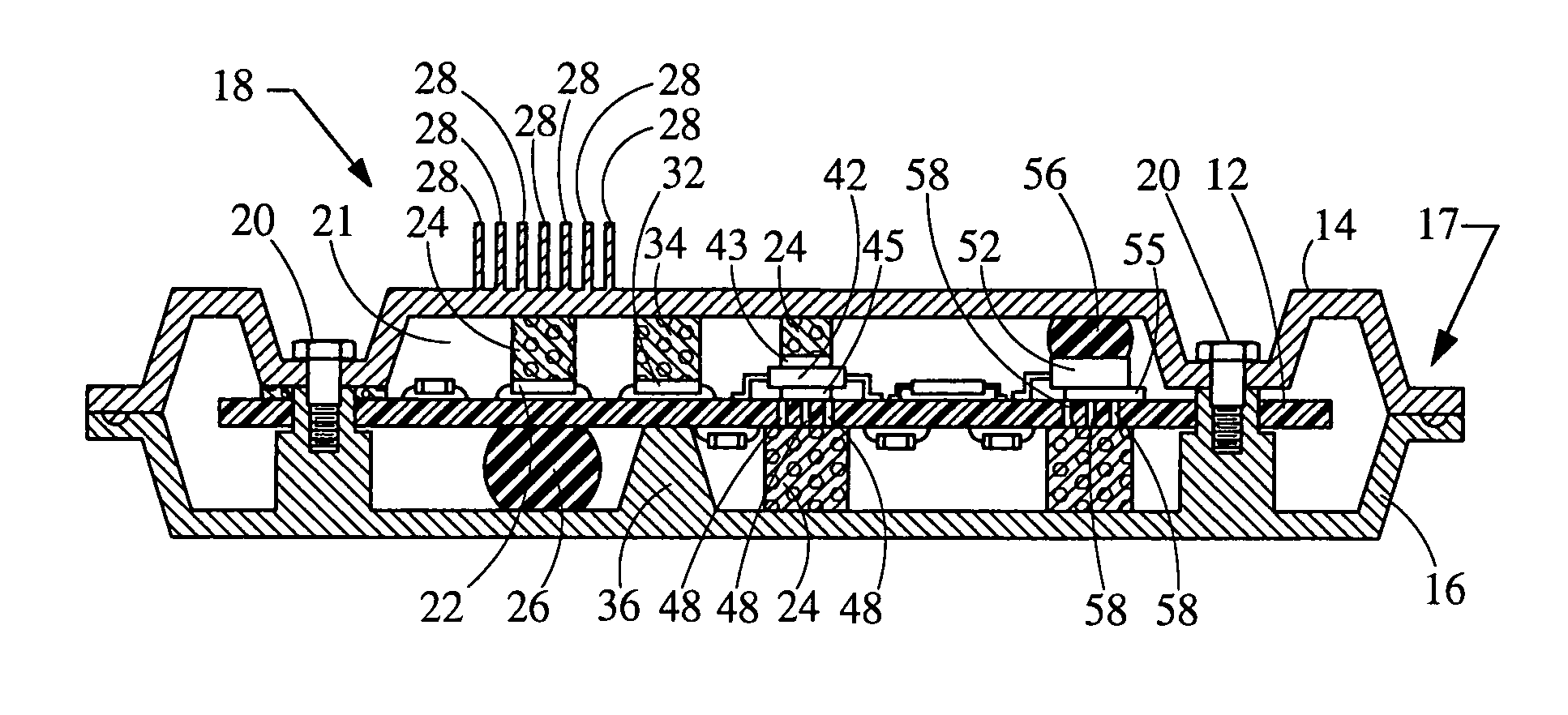
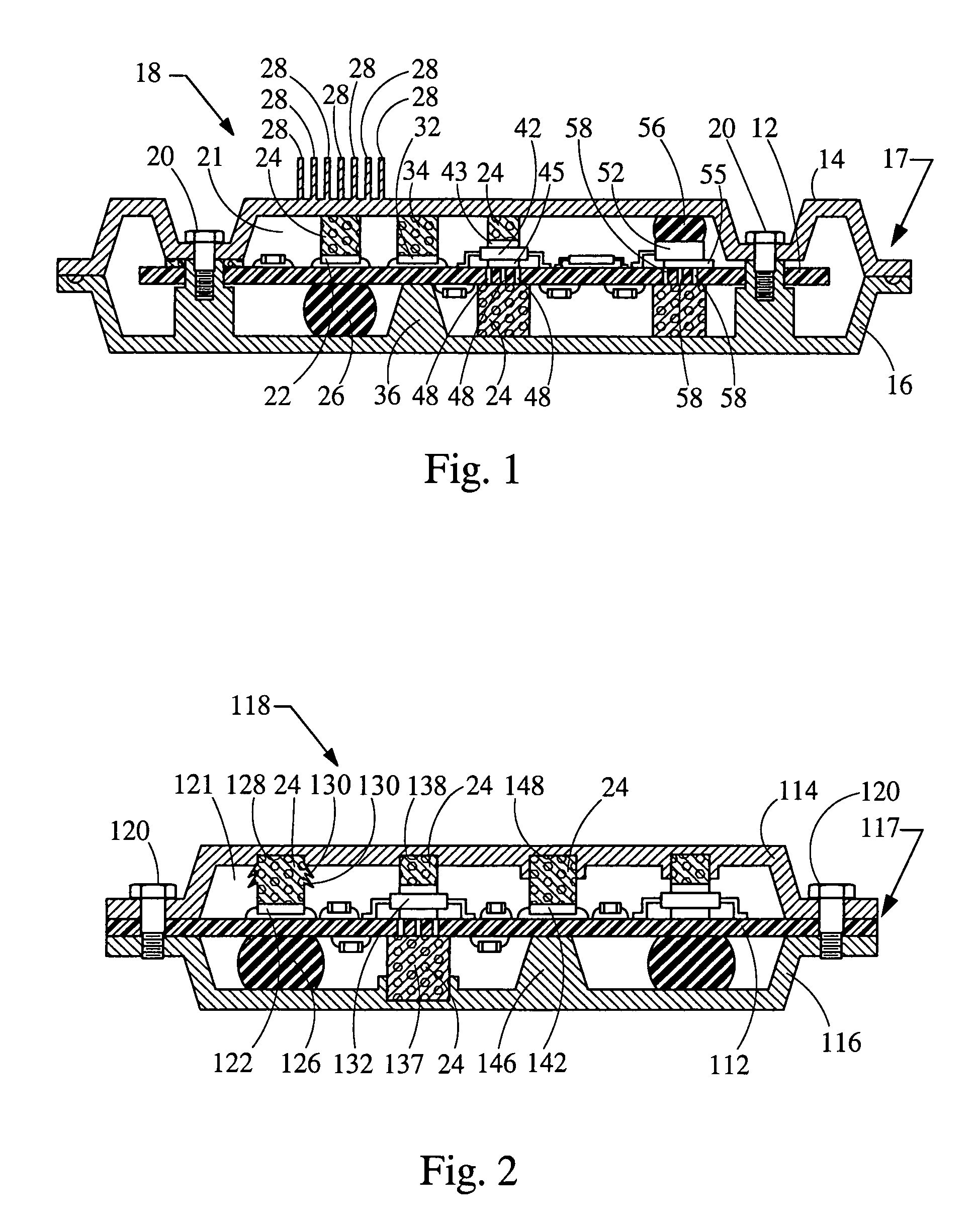
[0024]Referring now to FIG. 1, a electronic assembly 18 configured to transfer heat from an electrical component embodying the principles of the present invention is illustrated therein. Assembly 18 includes an electrical component 22 and an elastically deformable member 24. Electronic assembly 18 has a circuit board 12 with electrical components mounted on the circuit board 12. Electronic assembly 18 also has a housing 17 including a top half 14 and a bottom half 16 that are fastened together with screws 20 to protect and support the printed circuit board 12. Heat generated by electrical components 22 needs to be conducted away from the electrical components to provide for the proper functioning of the electrical components.

[0025]The elastically deformable member 24 contacts electrical components 22 at a first end and housing 17 at a second end. In an embodiment of the present invention, deformable member 24 is attached to the housing 17 and is compressed between the housing 17 and...


PUM


Abstract

The present invention provides a system for conducting heat away from an electrical component wherein the system has an elastically deformable member providing thermal communication with an electrical component. The system for conducting heat energy in an electronic assembly includes an electrical component, an elastically deformable member, and a housing. The elastically deformable member is placed in a compressed position between the electrical component and the housing such that the elastically deformable member is fixed into an assembled location. The elastically deformable member conducts heat energy away from the electrical component into the housing where it is dissipated into the environment. Since the compressed position fixes the location of the elastically deformable member, the system does not require a mechanical fastening to the electrical component thereby reducing thermo-mechanical fatigue. The elastically deformable member is made of a metal material allowing it to easily conduct the heat energy.

Description

CROSS REFERENCE TO RELATED APPLICATION[0001]The present invention claims priority to U.S. Provisional Application Ser. No. 60 / 387,621, filed Jun. 10, 2002, entitled “Power electronics thermal management”.BACKGROUND[0002]1. Field of the Invention[0003]The present invention generally relates to a system for transferring heat from electrical components.[0004]2. Description of Related Art[0005]Thermal management is a critical issue that must be considered during the development of electronic assemblies. With the advances in the functionality of electrical components, power and heat dissipation requirements for electronic assemblies have increased. In addition, the development of bare die packages that do not have housings or heat sinks has created a need for systems and methods that can conduct the heat away from the silicon die. Current methods include physical interconnects which have the undesired effect of increasing the thermo-mechanical fatigue applied to the electronic assembly.[...

Claims


Application Information

Patent Timeline
Patent Type & Authority Patents(United States)
IPC IPC(8): H05K7/20H05K1/02
CPCH05K7/2049H05K7/20454H05K1/0206
Inventor GLOVATSKY, ANDREW Z.JAIRAZBHOY, VIVEK
Owner VISTEON GLOBAL TECH INC
Learn More