
Methods and systems for target detection

a target detection and target technology, applied in the field of target detection, can solve the problems of large, bulky, heavy, and inconvenient operation of current systems for detecting and tracking targets marked with taggants, and achieve the effects of reducing the cost of operation, and reducing the number of people carrying and operating the system

Active Publication Date: 2014-02-18
LOCKHEED MARTIN COHERENT TECH +1
View PDF7 Cites 3 Cited by
  • Summary
  • Abstract
  • Description
  • Claims
  • Application Information

AI Technical Summary

Benefits of technology

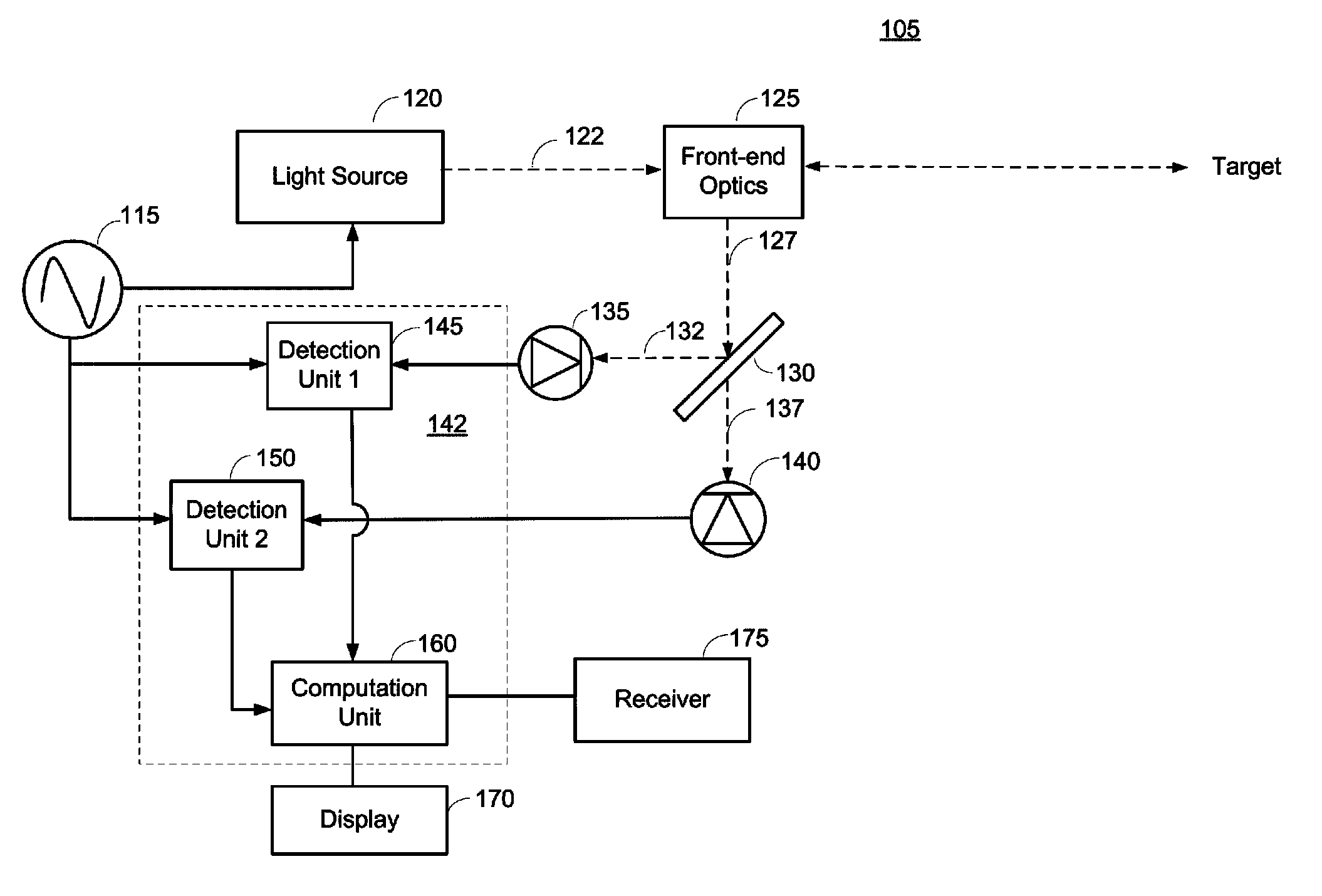
The patent is for a tiny target system that can be carried and operated by one person. It consists of a low power light source, front-end optics, an optical filter, and two detectors. The light source creates a continuous wave of light that is modulated at a certain frequency, which is then directed to a target that may be tagged with a fluorescing material. The front-end optics collect the light that comes back from the target, separating out the elastic light scatter and the fluorescing light. The intensity of both the elastic light scatter and the fluorescing light is then detected separately by a first and a second detector. The system calculates the amplitude and phase of these signals, and can determine if the target is aligned with the target system and identify the taggant on the target. It can also determine the distance of the target and the lifetime of the taggant. The target system can therefore perform various functions such as target detection, range determination, taggant detection, and taggant discrimination.

Problems solved by technology

Current systems for detecting and tracking targets marked with a taggant are often large, bulky and incorporate an active light source having large peak powers that are unsafe for humans.
While these systems can have operating ranges that reach beyond a kilometer, they are too large, heavy and consume too much power to be carried and operated by an individual (e.g., a soldier).

Method used


Image

  • Methods and systems for target detection
  • Methods and systems for target detection
  • Methods and systems for target detection

Examples


Embodiment Construction

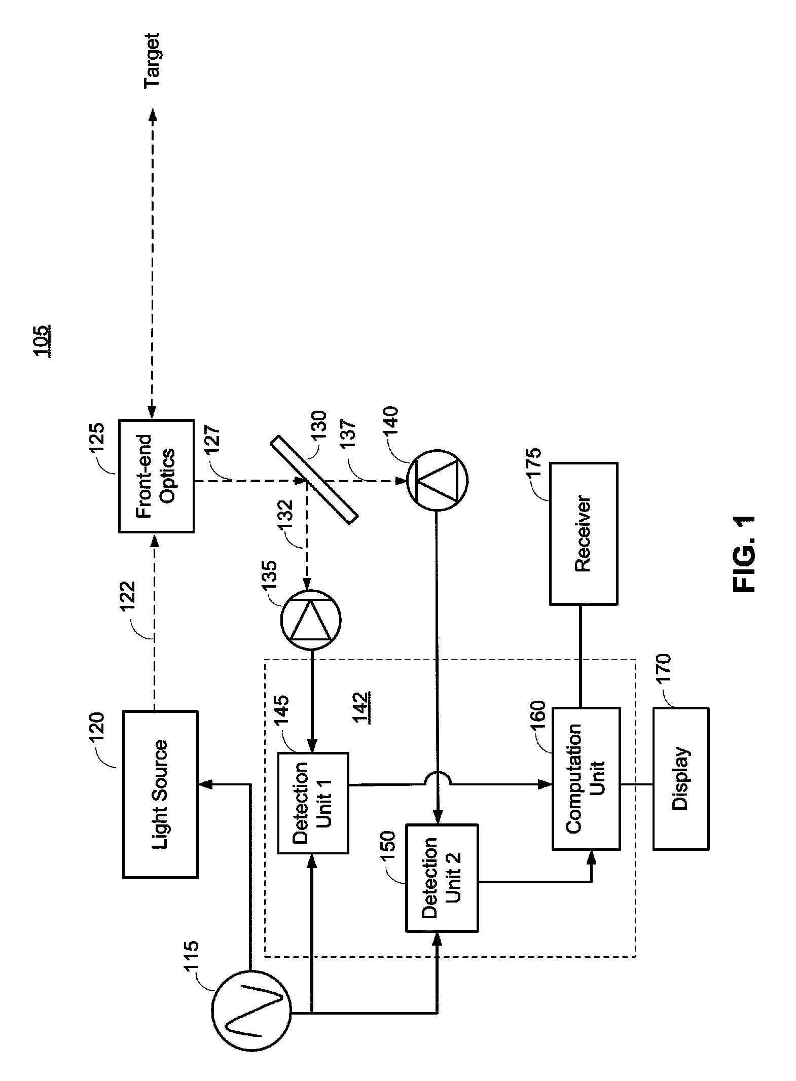
[0018]FIG. 1 is a block diagram illustrating a target system 105 for detecting and tracking a target marked (tagged) with a fluorescent taggant according to an embodiment of the present invention. The taggant may comprise a fluorescent material that absorbs incoming light and reemits light at a different wavelength (e.g., longer wavelength). Various examples of taggant materials that may be used are discussed further below. A target of interest may be marked with a taggant by dispersing the taggant in the vicinity of the target using an explosive detonation or projectile. The target system 105 may be used to provide one or more of the following functions: 1) target detection, 2) range determination, 3) taggant detection, and 4) taggant discrimination / confirmation. Each of these functions is described in further detail below.

[0019]The target system 105 comprises a reference oscillator 115, a light source 120, front-end optics 125, an optical filter 130, a first photodetector 135, a s...


PUM


Abstract

Various aspects of the disclosure provide a target system that is small and low power. In one embodiment, the target system transmits an intensity modulated light beam to a target (which may be tagged with a fluorescent taggant), collects the resulting return light from the target, and separates out elastic light scatter and fluorescent light in the collected light. The intensities of the elastic light scatter and the fluorescent light are then separately detected by first and second photodetectors, respectively. The first photodetector generates an elastic scatter detection signal based on the detected elastic light scatter and the second photodetector generates a fluorescent detection signal based on the detected fluorescent light. The elastic scatter detection signal and / or the fluorescent detection signal are used to provide one or more of the following functions: 1) target detection, 2) range determination, 3) taggant detection, and 4) taggant discrimination / confirmation.

Description

STATEMENT REGARDING FEDERALLY SPONSORED RESEARCH OR DEVELOPMENT[0001]Not applicable.FIELD[0002]The present invention generally relates to target detection and, in particular, relates to detection of a target marked with a taggant.BACKGROUND[0003]Fluorescent taggants can be used to mark and track targets, e.g., in a military setting or other setting. The taggant may comprise a material that fluoresces when illuminated by a target system. A target of interest may be marked (tagged) with a taggant by dispersing the taggant in the vicinity of the target using an explosive detonation or projectile, thereby coating the target with the taggant. There are, of course, other ways to tag a target.[0004]Current systems for detecting and tracking targets marked with a taggant are often large, bulky and incorporate an active light source having large peak powers that are unsafe for humans. While these systems can have operating ranges that reach beyond a kilometer, they are too large, heavy and c...

Claims


Application Information

Patent Timeline
IPC IPC(8): G01S17/36
CPCG01S17/32G01S7/4802G01S7/4816G01S17/74G01S17/36G01S17/026G01S17/04
Inventor GLENNON, JOHN, J.
Owner LOCKHEED MARTIN COHERENT TECH
Learn More