
Method and device for determining the topography of a material surface

a technology of topography and material surface, applied in the direction of angle measurement, navigation instruments, instruments, etc., can solve the problems of erroneous value of contact surface, insufficient detail information about contact surface properties, and blank surface portions

Inactive Publication Date: 2014-02-18
IND PHYSICS HLDG +1
View PDF7 Cites 0 Cited by
  • Summary
  • Abstract
  • Description
  • Claims
  • Application Information

AI Technical Summary

Benefits of technology

[0013]The aim of the present invention is to provide a method and a device wherein the drawbacks of the so far known techniques are avoided or at least reduced.
[0015]In an ordinary printing process, a paper web is transferred at great velocity through a printing nip with a high nip load with which the paper becomes compressed. A point on the paper web normally remains in the printing nip during a very short time, typically 10-50 milliseconds (ms).
[0016]The invention offers the possibility of performing quality control of the printing properties of a material and in particular of a paper, with a more relevant measuring method, which can be performed fast and simple in connection with the production by ordinary, not specially trained, operating personnel. With the method suggested here, a single measurement only takes a few seconds to carry through. The method according to this invention gives an image of the paper in a condition which well corresponds to the conditions that prevail at the very printing event.

Problems solved by technology

If at all places on the printing area of the paper such a contact is not obtained, ink dots not coming into contact with the paper surface will be missing on the printed surface (“missing dots”) which causes blank surface portions or, sometimes in case of multi-colour printing, tinting.
All established measuring methods have one or more drawbacks, since on the one hand they may be time-consuming to use, on the other hand they give insufficient detail information about the properties of the contact surface.
For that reason the Chapman method gives an erroneous value of the contact surface, since it compresses the measuring area during an essentially longer time compared to the conditions in a printing press.

Method used


Image

  • Method and device for determining the topography of a material surface
  • Method and device for determining the topography of a material surface
  • Method and device for determining the topography of a material surface

Examples


Embodiment Construction

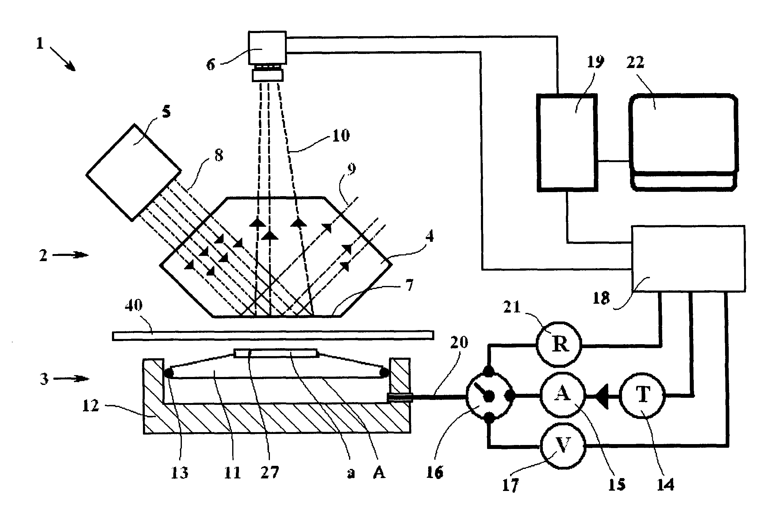
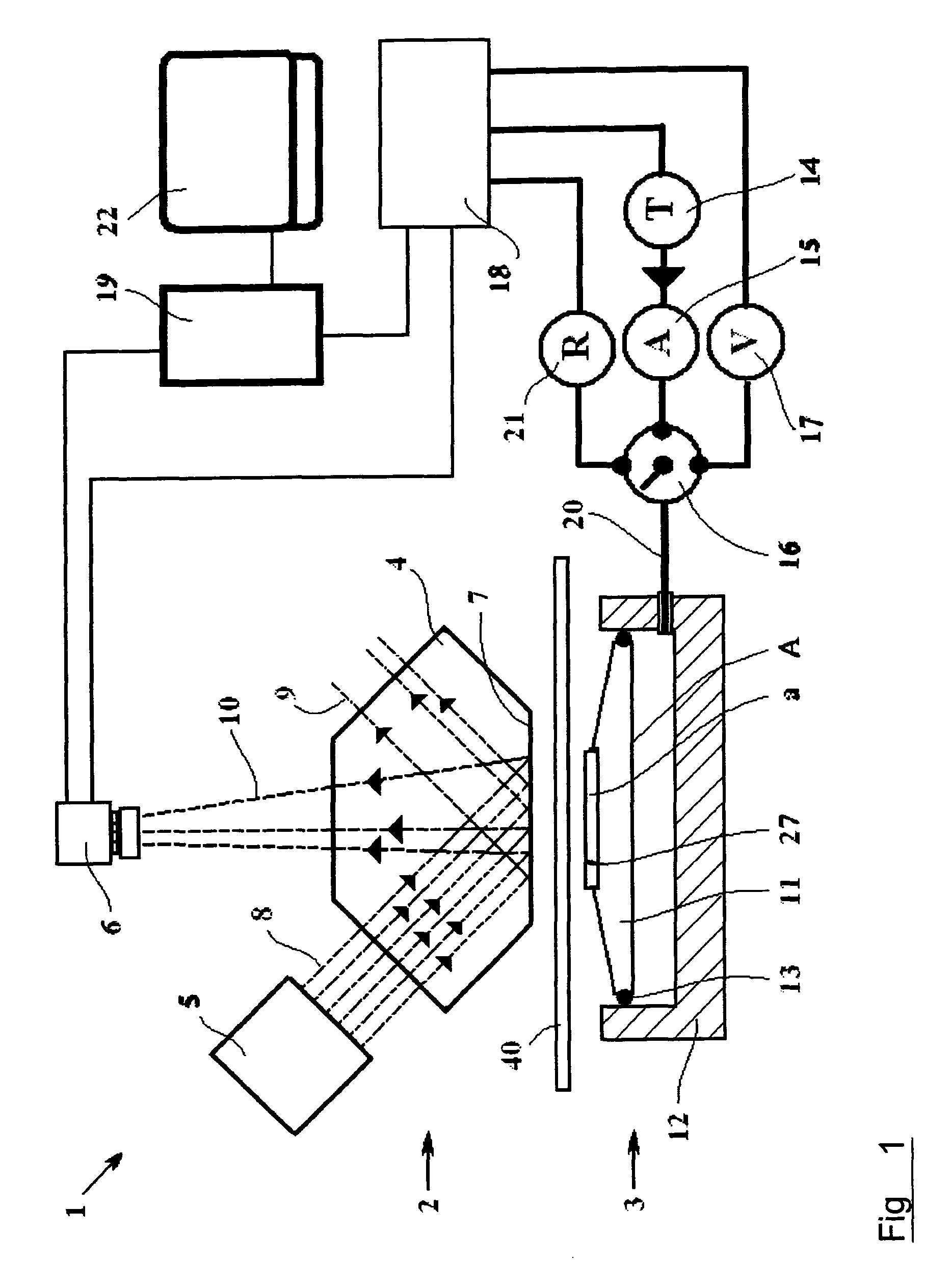
[0034]With reference numeral 1 is generally indicated a device according to the invention for determining the dynamic topography of a material surface and in particular the surface of a paper, in relation to its ability to receive a print through mechanical contact.

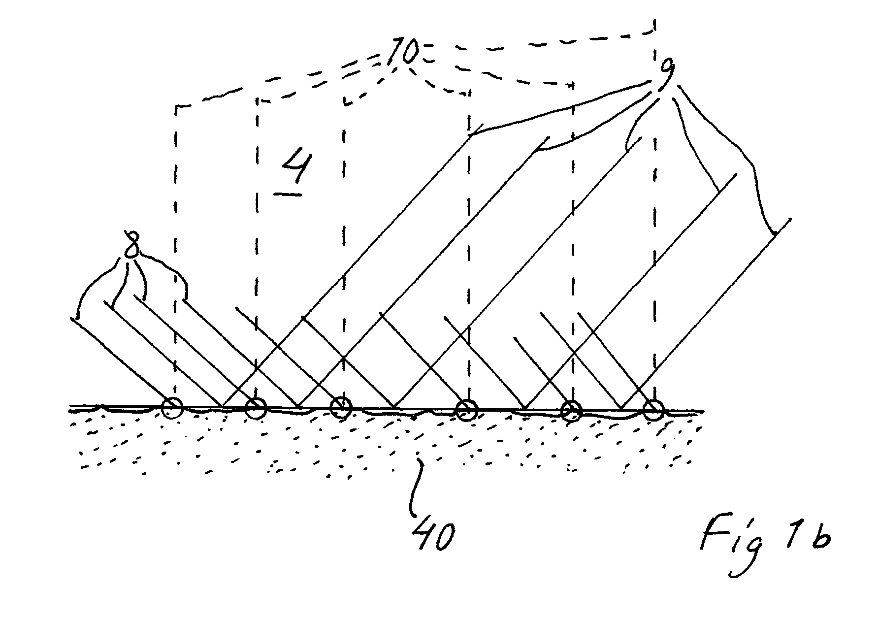
[0035]The device 1 includes an illuminating and representation unit 2 and a compression unit 3. The unit 2 includes a prism 4 which can be of the Chapman prism type, an illumination device 5 and a camera 6 with associated lens system. The lower surface of the prism 4, as seen on the image, is a clamping surface 7. The beam path from the illumination device 5 is indicated with broken lines, wherein with 8 is indicated light inciding against the clamping surface 7 of the prism and with 9 reflected light from the clamping surface on the prism where there is no contact with the surface of the test piece.

[0036]In the portions of the contact surface against which the paper come into contact, according to the above, the inciding...


PUM


Abstract

A method and a device for determining a topography under load of the surface of a material, wherein a test piece (40) of the material intended to be determined is subjected to a compression with a determined load between a first and a second clamping surface (7, 27), after which, in a compressed state, at least one representation is made of surface portions of the material that are in contact with at least one of said clamping surfaces (7, 27), and that the representation is evaluated. The compression is controlled in respect of its speed for obtaining said predetermined load, and said at least one representation is made at a chosen point in time or chosen points in time during this process.

Description

FIELD OF THE INVENTION[0001]The invention concerns a method and a device for determining the topography of a material surface according to the preambles of the respective independent claims.BACKGROUND OF THE INVENTION[0002]In most commercial printing processes (for example flexography, intaglio printing and lithography), printing ink is transferred to a paper surface through direct mechanical contact. Since the printed image is formed by a number of small screen dots having diameters of 5-50 μm, it is important to achieve good contact over the entire printing surface. If at all places on the printing area of the paper such a contact is not obtained, ink dots not coming into contact with the paper surface will be missing on the printed surface (“missing dots”) which causes blank surface portions or, sometimes in case of multi-colour printing, tinting.[0003]A number of different solutions are known in order to investigate properties of different paper surfaces with regard to the “topo...

Claims


Application Information

Patent Timeline
Patent Type & Authority Patents(United States)
IPC IPC(8): G01B11/30
CPCG01B11/303G01N33/346
Inventor BOSTROM, BERNT
Owner IND PHYSICS HLDG
Learn More