
End-to-end service quality monitoring method and system in a radio network

a radio network and end-to-end service quality technology, applied in the direction of transmission monitoring, data switching network, wireless commuication services, etc., can solve the problems of incompatibility between certain models or versions of wireless network equipment and user equipment, affecting the end user experience, and regular damage to wireless networks, so as to prevent data security threats, and ensure service availability

Active Publication Date: 2014-02-18
7SIGNAL OY
View PDF14 Cites 12 Cited by
  • Summary
  • Abstract
  • Description
  • Claims
  • Application Information

AI Technical Summary

Benefits of technology

[0047]In one embodiment of the invention, key performance indicators for the network are calculated using at least one of measured radio network signal to noise ratios, probe response times, amount of retransmissions, amount of transmitted data frames or used data rates or codecs between clients and access points or between equal network nodes or between monitoring stations and other network nodes. The purpose of the present invention is to ensure continuous availability of the service, good service quality for different applications and to prevent data security threats on the radio interface.
[0048]One advantage for the present invention is that it enables the measurements of true service quality as it is experienced by the end user. This is possible with different applications without any notable disturbance in the functionalities of the network. Using directive multi-beam antennas increases the coverage of one monitoring station and minimizes the number of needed stations. Use of directive antennas with active testing limits the spreading of the RF power only to a small sector at a time. This is essential for minimizing impact to other wireless traffic in the network. The present invention enables the locationing of the interfering signal sources, the bottle necks of the networks which restrict the service quality and it enables the monitoring of the service level agreements in different areas of the network and also in end-to-end connection routes as experienced by end users.
[0049]One benefit of the invention for the business point of view is that the operational costs in the network are lowered. Less personnel are needed for operating and maintaining even a diverse network. The method monitors the network and is able to trigger alarms automatically around the clock seven days a week. This enables fast detection of any problems in the network. Associated performance trending capability enables the prediction of network problems already before they are experienced by the users. Predicted network maintenance needs may this way be performed at the least disturbing time. All this leads to higher uptime, more satisfied customers and clear monetary business benefits. Furthermore, the invention enables remote monitoring from e.g. the premises of an external operator. This enables outsourcing network operation to an external network operator that otherwise would have no visibility to company internal network. With no visibility, very rare operators are willing to take responsibility of the company internal wireless network. Additionally, when there is a continuous visibility to network capacity usage and performance, there is no need to initially overdimension the wireless network capacity. Full visibility to user experience enables further investments to network capacity increase when there is a clear need for it.

Problems solved by technology

Wireless networks also regularly suffer from technology related issues significantly impacting to end user experience.
Certain models or versions of wireless network equipment and user equipment may be incompatible.
Amount of combinations is so high that testing everything against each others is impossible task for equipment manufacturers.
These types of issues cause regularly problems with users accessing and using wireless services.
This means that cell may be visible to end users, but cannot provide any traffic or service.
This may be related to a fault in the equipment, where each software version may behave differently in this sense.
The monitoring of the radio interface only is not sufficient.
On the other hand, the monitoring of the wired connection only, is not sufficient either.
Prior art systems are not capable of detecting these kinds of network behavior and thus, this makes the network vulnerable to degraded service quality.
WIDPS measurements are focused on data security monitoring and their capability to monitor end-to-end service quality is very limited.
The first shortcoming with the WIDPS is that due to modest RF and antenna technology, it requires a vast amount of monitoring stations in the network area in order to work properly.
A further problem in the prior WIDPS solutions is that they enable only passive measurements and provide no end-to-end service quality visibility or information about the bottlenecks in the network.
Furthermore, WIDPS does not have support for mobility, like GPS positioning of the monitoring station.
Additional issues with the switch-based solution is that it works only with Wireless LAN systems, scales poorly to larger configurations and requires a dedicated connection between the switch and access / monitoring point.
Due to high operative cost related to dedicating transmissions lines to each access / monitoring point, this makes it practically impossible to manage a spread out network with this solution.
A fault in the switch may take down the whole wireless network under it.
This even further increases the amount of switches and the costs in the switch-based solutions.
Finally, a disadvantage is that the switch-based solution is non-mobile and it is not suitable for measuring the quality of service in view of the end user.
The main problem in these solutions for LAN is the lack of support for any RF measurements or for any data security measurements through radio interface.
Thus they do not support any mobility, any wireless technologies or centralized network management that are crucial for any wireless network.
These systems do not offer full end user experience monitoring, they lack support for mobility and location related measurements.
The main problem in prior art is that the end-to-end service quality for the large and spread out wireless broadband networks cannot be monitored in any efficient and reliable manner.

Method used


Image

  • End-to-end service quality monitoring method and system in a radio network
  • End-to-end service quality monitoring method and system in a radio network
  • End-to-end service quality monitoring method and system in a radio network

Examples


Embodiment Construction

[0057]Reference will now be made in detail to the embodiments of the present invention, examples of which are illustrated in the accompanying drawings.

[0058]The present invention presents a method and system for performing network performance monitoring in mobile communication networks achieving service quality data, for instance. The method can be implemented in several kinds of networks, such as for example in WLAN and WiMAX networks (networks supporting the IEEE 802.16 standard). Also Flash-OFDM technology and VoIP over WiFi technology are useful applications for the present invention. Nonetheless, use of the presented method is not restricted to these embodiments.

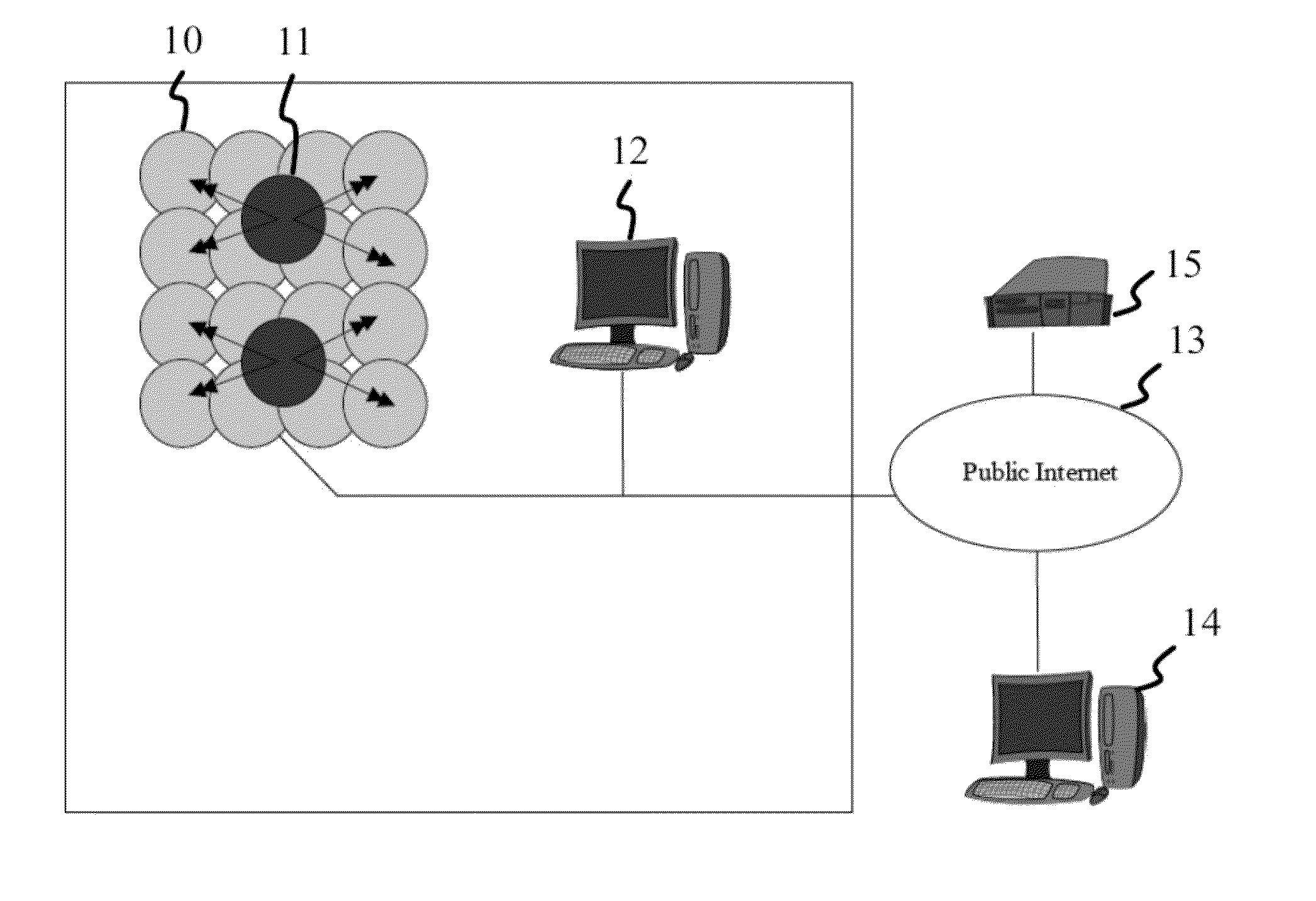
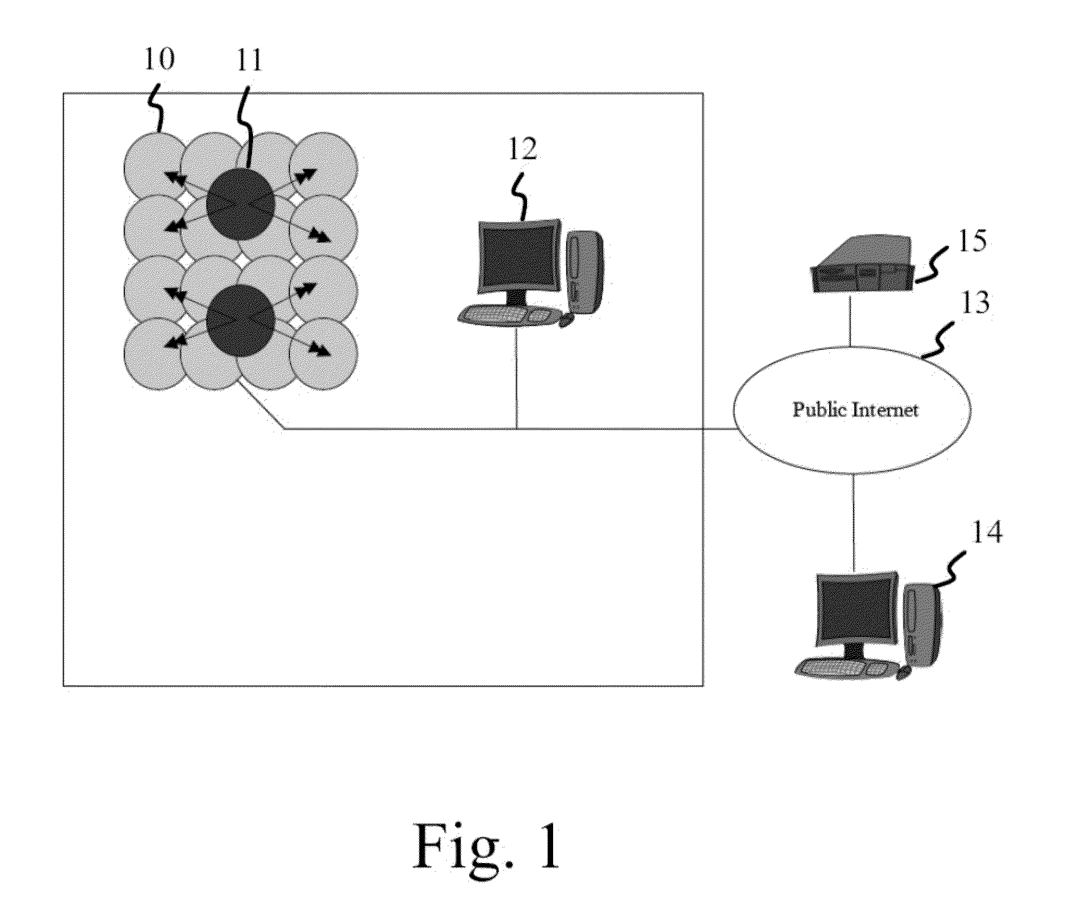
[0059]FIG. 1 discloses an example of the system used in the present invention. The illustration shows the main components of the apparatus. Each sphere 10 includes a WiFi (WLAN) access point with the region covered by each of them. In this example, there are two monitoring stations 11 placed in the area. The arrows orig...


PUM


Abstract

A method and a system for service quality monitoring in a network includes radio interfaces. The measurements are end-to-end measurements between the end user and chosen network element. The measurements are implemented using monitoring stations which can monitor the traffic passively or actively by transmitting test signals. The antenna beam directions of the monitoring stations can be controlled. The performance server works as a counterpart of the active tests. A reporting suite may define the performed measurements and it also collects the measurement data from different monitoring stations. Monitoring data from several corporate intranets can also be collected to an external server through internet connection.

Description

BACKGROUND OF THE INVENTION[0001]1. Field of the Invention[0002]The present invention relates to continuous monitoring and quality parameter measurements in wireless broadband networks.[0003]2. Description of the Related Art[0004]In a wireless networks it is important to ensure good quality for the data traffic in the network. Quality can be verified and efficiently maintained by monitoring the functionalities of the wireless network with appropriate apparatus and procedures. The monitoring of the network reveals whether desired connection or services are available or whether a sufficient quality level for the connection is reached. Furthermore, monitoring is used for revealing any security attacks performed by a third party on a radio signal interface or through other interfaces.[0005]New applications which often are provided by e.g. WLAN networks, WiMAX technologies and in Flash-OFDM technologies, require larger capacity and better quality than earlier. One such application is ‘Vo...

Claims


Application Information

Patent Timeline
Patent Type & Authority Patents(United States)
IPC IPC(8): H04L12/26H04L41/0677H04L41/0681H04L41/147H04L41/50H04L43/06H04L43/08H04L43/16H04L43/55
CPCH04L43/0864H04L43/00H04L43/10H04L12/2602H04L43/0852H04L43/0811H04L41/147H04L43/16H04W24/06H04W24/08H04W88/08H04L41/149H04B17/00H04W64/00H04W88/18H04W68/00H04W24/04
Inventor KETONEN, VELI-PEKKA
Owner 7SIGNAL OY
Learn More