Filling degree gauge, agricultural vehicle with the gauge, and method of measuring and displaying residual filling potential of target area

a technology of agricultural vehicles and gauges, applied in the field of filling degree gauges, can solve problems such as laying a heavy burden on operators, and achieve the effect of facilitating further possibilities and relieving operators of stress

Active Publication Date: 2014-02-25
CLAAS E SYST GMBH
View PDF9 Cites 34 Cited by
  • Summary
  • Abstract
  • Description
  • Claims
  • Application Information

AI Technical Summary

Benefits of technology

[0017]In view of this prior art it is an object of the present invention to facilitate further the possibilities of a human operator of an agricultural vehicle of monitoring the process of filling a target area, such as a container, through a target, such as an open top of the container, and relieve the operator of stress.
[0018]This is obtained by providing a filling degree gauge for measuring and displaying a residual filling potential of a target area being filled through a target with goods by means of a goods carrier of an agricultural vehicle, especially a discharge spout of a forage harvester, said filling degree gauge comprising a 3D sensor for observing at least a part of the target area including at least a part of the target, a data control system and a visual display unit, said data control system operating to provide on the visual display unit a visual display indicating residual filling potential by indicating the current one of at least three different levels of residual filling potential. Hereby is obtained that the operator readily may realize the state of filling of the target area, without being stressed because the target area is suddenly full.
[0021]In one embodiment the local areas are fixed relative to the 3D sensor. Hereby is obtained that the operator may readily realize how the goods carrier should be moved relative to the target area and when.
[0023]In a further embodiment the local areas and boundaries thereof are floating in dependence on levels of residual filling potential. Hereby the operator may readily realize which area has a given residual filling potential.
[0026]In a preferred embodiment the data control system operates to provide on the visual display unit a visual display indicating the local residual filling potential as a 2D graph. In one embodiment the data control system operates to provide on the visual display unit a visual display indicating said 2D graph in a 2D coordinate system in which one axis represents position in the target area and another axis represents filling degree, and in an alternative or supplementary embodiment the data control system operates to provide on the visual display unit a visual display indicating at least a part of the target area and the level of residual filling potential of local areas within said part of the target area, preferably by indicating mean local residual filling potential for parallel bands of the target area. Hereby the operator may readily obtain an overview of the overall filling status of the target area.
[0027]In a preferred embodiment an imaging device is provided for imaging at least a part of the target area including at least a part of the target, and the data control system operates to display an image provided by the imaging device on the visual display unit together with the visual display indicating residual filling potential. Preferably one of the displayed image and the visual display indicating residual filling potential is superposed on the other, whereby preferably the superposed display is transparent. Hereby the operator's perception of the filling state of the target area is facilitated since the operator is able to observe a picture of the target area as well as the indication of the measured residual filling potential.

Problems solved by technology

The advanced and fast machines are demanding of control and would lay a heavy burden on their operators if not for automation.

Method used


Image

  • Filling degree gauge, agricultural vehicle with the gauge, and method of measuring and displaying residual filling potential of target area
  • Filling degree gauge, agricultural vehicle with the gauge, and method of measuring and displaying residual filling potential of target area
  • Filling degree gauge, agricultural vehicle with the gauge, and method of measuring and displaying residual filling potential of target area

Examples


Embodiment Construction

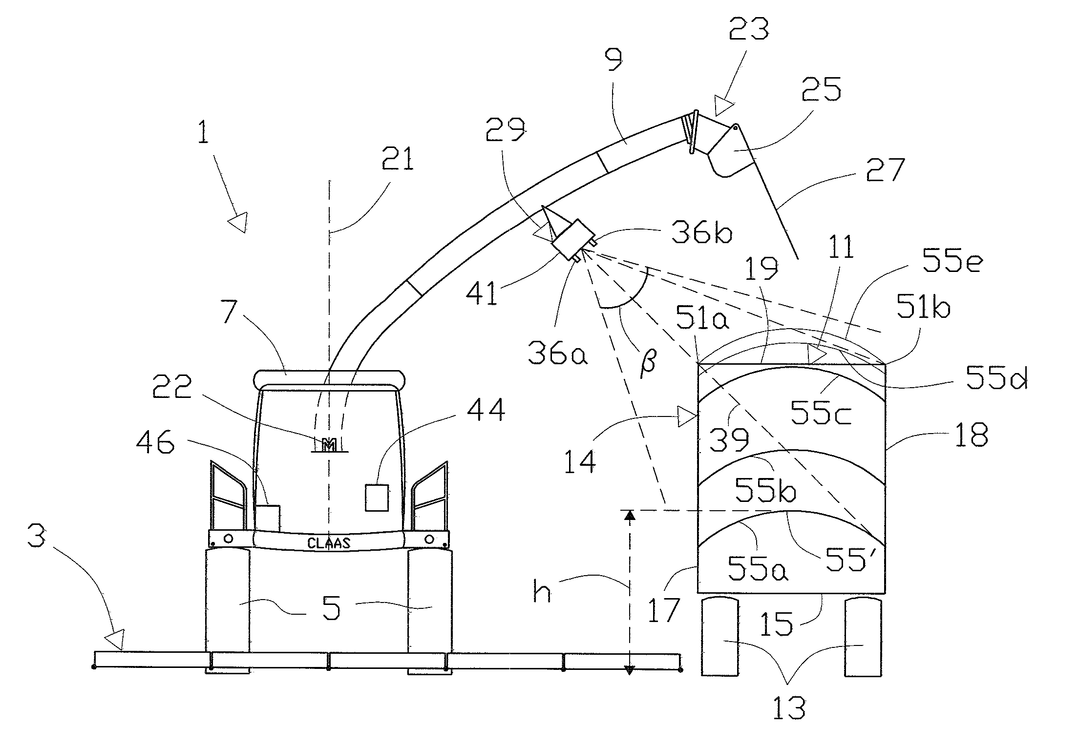
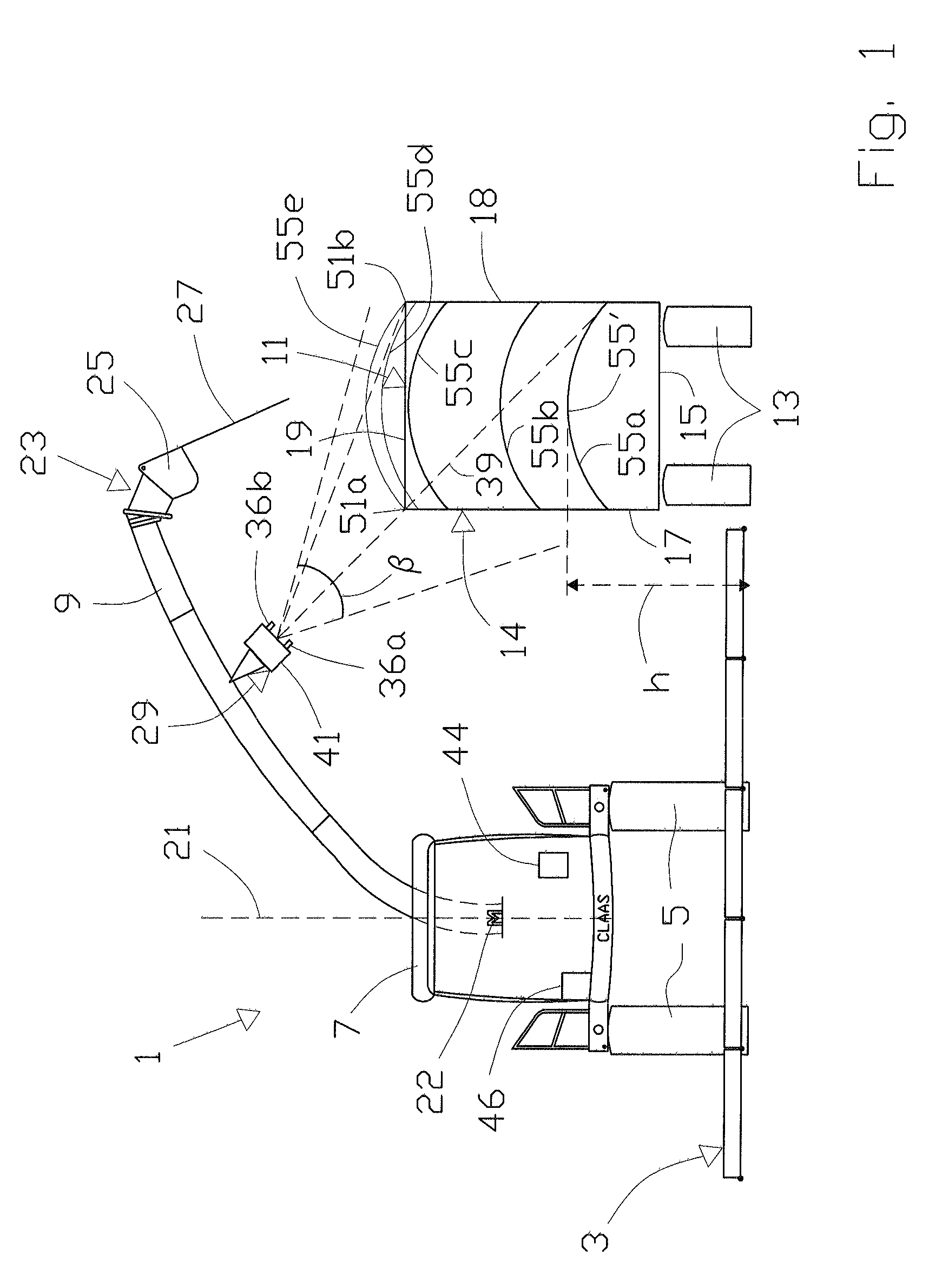
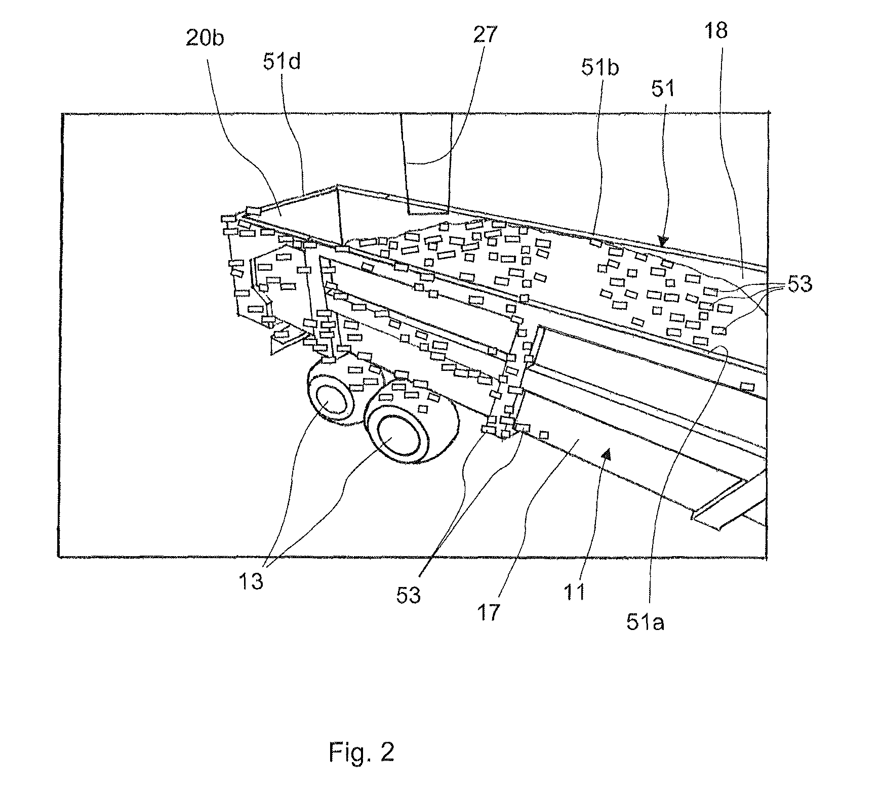
[0040]FIG. 1 shows in a front view a forage harvester 1 with a header 3, ground wheels 5, a driver's cabin 7 and a goods carrier in the form of a discharge or ejecting spout 9. During work the header 3 will harvest a crop, which is processed by the harvester 1 and ejected from the spout 9. To collect the ejected crop a transport wagon 11 is driven alongside the forage harvester 1. Of the transport wagon 11 only ground wheels 13 and a crop-carrying container 14 with a bottom 15, sidewalls 17, 18 and an open top 19, is shown in FIG. 1. Thus during operation the crop-carrying container 14 constitutes a target area to be filled with goods or crop and the open top 19 constitutes a target through which the goods must enter the target area.

[0041]The spout 9 is in a manner known per se mounted on the harvester 1 to be rotatable in a controlled manner around a vertical axis 21 by means of actuators indicated by numeral 22. A gauge is attached to the actuator 22, whereby the position of the s...


PUM

PropertyMeasurementUnit
residual filling potentialaaaaaaaaaa
3D imagingaaaaaaaaaa
areaaaaaaaaaaa

Abstract

A filling degree gauge for measuring and displaying a residual filling potential of a target area, such as a container, being filled through a target, such as an open top, with goods by a goods carrier, such as a discharge spout, of an agricultural vehicle, such as a harvester, has a 3D sensor for observing at least a part of the target area including at least a part of the target, a data control system and a visual display unit. The data control system operates to provide on the visual display unit a visual display indicating residual filling potential by indicating the current one of at least three different levels of residual filling potential.

Description

CROSS-REFERENCE TO RELATED APPLICATION[0001]The invention described and claimed hereinbelow is also described in European Patent Applications EP 09170842.0 filed on Sep. 21, 2009 and EP 09169622.9 filed on Sep. 7, 2009. These European Patent Applications, whose subject matter is incorporated here by reference, provide the basis for a claim of priority of invention under 35 U.S.C. 119(a)-(d).[0002]The present application contains a subject matter which can be similar to the subject matter disclosed in U.S. patent application Ser. No. 12 / 868,885 filed Aug. 26, 2010.BACKGROUND OF THE INVENTION[0003]The present invention relates a filling degree gauge for measuring and displaying a residual filling potential of a target area being filled through a target with goods by means of a goods carrier of an agricultural vehicle, especially a discharge spout of a forage harvester.[0004]The invention further relates to an agricultural vehicle comprising a filling degree gauge and a method of contr...

Claims


Application Information

Patent Timeline
Patent Type & Authority Patents(United States)
IPC IPC(8): B65B1/04A01D41/127B65G67/22G09G5/00G06F19/00
CPCB65G67/04B65G2203/041A01D43/087B65G67/32
Inventor MADSEN, TOMMY ERTBOLLEBLAS, MORTEN RUFUSKIRK, KRISTIAN
Owner CLAAS E SYST GMBH
Why Eureka
Try Eureka