
Ring shear apparatus considering wall-slip effect

a technology of ring shear and wall-slip, which is applied in the direction of apparatus for force/torque/work measurement, fluid pressure measurement, instruments, etc., can solve the problems of social and economic losses over the living of people, difficulty in identifying the movement of the slope with naked eyes, and rights to be deteriorated, so as to improve the accuracy of measurement

Active Publication Date: 2014-02-25
KOREA INST OF GEOSCI & MINERAL RESOURCES
View PDF11 Cites 14 Cited by
  • Summary
  • Abstract
  • Description
  • Claims
  • Application Information

AI Technical Summary

Benefits of technology

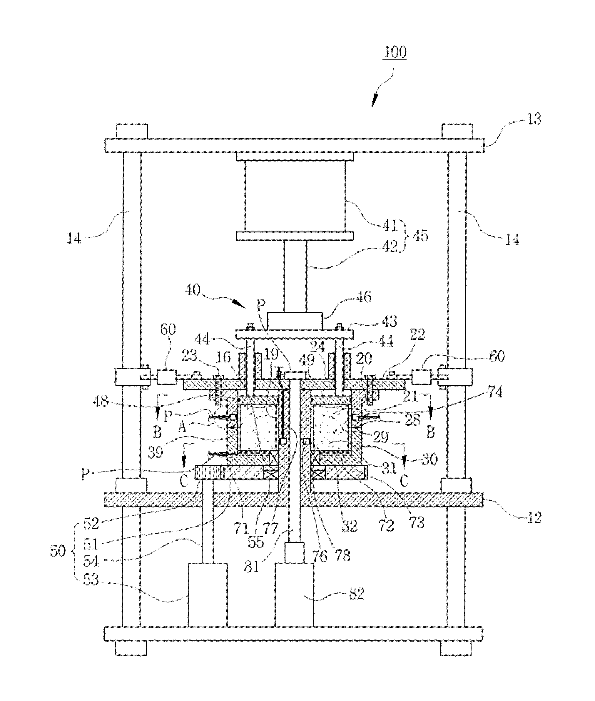
The present invention is a ring shear apparatus designed to accurately measure the strength of soil, which is important in predicting land slips and evaluating the movement of debris flows caused by land slips. The apparatus includes an upper and lower ring, with soil samples placed between them. The lower ring is attached to the upper ring and rotates relative to it. The apparatus also includes a rotating unit for rotating the lower ring, and a shear strength sensor combined with the upper ring for measuring the strength of the soil samples. The lower ring has protrusions on its inner surface to prevent the soil samples from sliding during rotation. The technical effect of this invention is to improve the precision of measuring the shear strength of soil samples and provide a reliable tool for predicting and preventing land slips.

Problems solved by technology

The occurrence of the debris flow that corresponds to movement after destruction is directly related to a damage of infrastructure.
In this case, the soil mass on the natural slopes shows a progressive action, and it is difficult to identify movements of the slopes with naked eyes.
Large and small landslips in Korea that take place due to annual isolated t-storms make living rights to be deteriorated, accompanied by social and economical losses over the living of people.
If the soil samples are slid between the upper ring and the lower ring, a torque of the ring shear apparatus is decreased, and an error occurs when the shear strength of the soil is measured at the upper ring and the lower ring.

Method used


Image

  • Ring shear apparatus considering wall-slip effect
  • Ring shear apparatus considering wall-slip effect
  • Ring shear apparatus considering wall-slip effect

Examples


Embodiment Construction

[0031]A ring shear apparatus considering a wall-slip effect (hereinafter referred to as a ‘ring shear apparatus’) according to an embodiment of the present invention will now be described more fully with reference to the accompanying drawings, in which exemplary embodiments of the invention are shown.

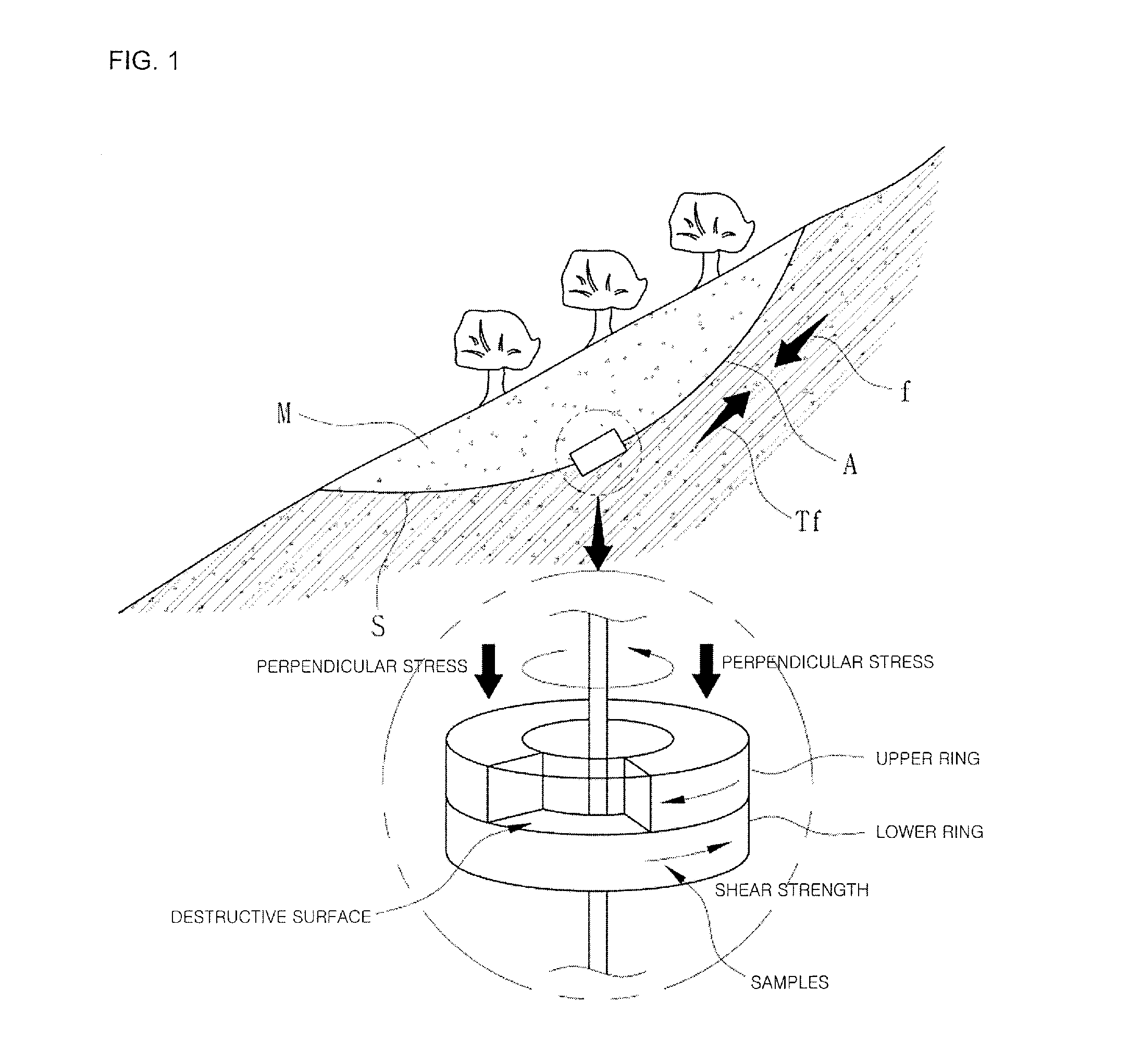
[0032]The ring shear apparatus according to the present invention is usually a test apparatus for providing basic data required for a warning system, such as prevention and measures for a landslip by evaluating slopes in a mountain district. In particular, the ring shear apparatus is to check a shear strength (shear resistance) of soil in a quantitative manner on various conditions, such as rainfall, gradient, drainage, saturation of an area (slope) where a landslip may take place.

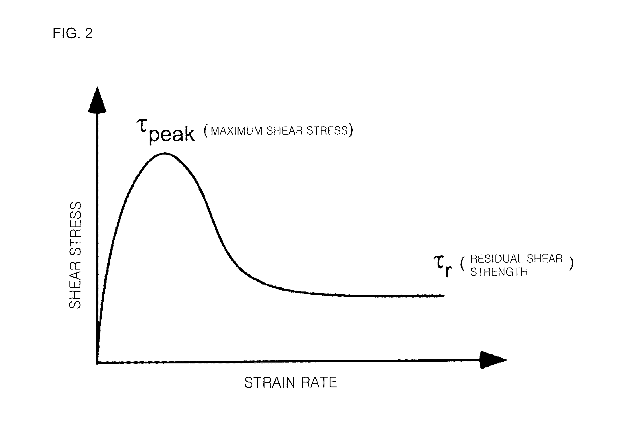
[0033]FIG. 1 is a schematic view of an object to be simulated of a ring shear apparatus according to an embodiment of the present invention, and FIG. 2 is a graph showing the relationship between a shear stren...


PUM

PropertyMeasurementUnit
speedaaaaaaaaaa
movement speedaaaaaaaaaa
speedaaaaaaaaaa

Abstract

A ring shear apparatus for measuring a shear strength of soil samples. The ring shear apparatus considering a wall-slip effect including: an upper ring for forming a first accommodation portion having a ring shape in which soil samples are accommodated; a lower ring for forming a second accommodation portion that corresponds to the first accommodation portion of the upper ring and has a ring shape in which soil samples are accommodated, closely attached to a lower portion of the upper ring and rotatably installed relative to the upper ring; a rotating unit for rotating the lower ring relative to the upper ring; and a shear strength measuring sensor combined with the upper ring and for measuring a shear strength of the soil samples, wherein a plurality of protrusions that protrudes from the lower ring is formed on an inner circumferential surface of the lower ring along a circumferential direction of the lower ring in order to prevent the soil samples from being slid when the lower ring is rotated.

Description

CROSS-REFERENCE TO RELATED PATENT APPLICATION[0001]This application claims the benefit of Korean Patent Application No. 10-2011-0116606, filed on Nov. 8, 2011, in the Korean Intellectual Property Office, the disclosure of which is incorporated herein in its entirety by reference.BACKGROUND OF THE INVENTION[0002]1. Field of the Invention[0003]The present invention relates to a technology for reducing a natural disaster relating to a landslip, and more particularly, to a ring shear apparatus that may measure a shear strength that is a significant factor in evaluating the mobility of the landslip.[0004]2. Description of the Related Art[0005]Landslips take place when a soil mass slides along a thin soil layer above a bedrock due to external causes, such as an earthquake, isolated t-storms, thawing, and the like. Landslips in Korea usually take place due to isolated t-storms.[0006]Slopes formed by landslips form action destructive surfaces gradually and undergo continuous sliding (slope ...

Claims


Application Information

Patent Timeline
Patent Type & Authority Patents(United States)
IPC IPC(8): G01N3/32
CPCE02D17/20G01N3/24G01N33/24
Inventor JEONG, SUENG-WONSONG, YOUNG-SUKLEE, CHOON OHKIM, KYEONG-SU
Owner KOREA INST OF GEOSCI & MINERAL RESOURCES
Learn More