Folding frame for an agricultural implement

a technology for agricultural implements and folding frames, which is applied in the direction of soil-working methods, adjusting devices, agricultural tools and machines, etc., can solve the problems of shimmy, damage to the toolbar and other parts of the implement, and the narrowing of the folded implement has proved untenable, etc., to achieve the effect of retaining flexibility in use and variable windrow widths

Active Publication Date: 2014-02-25
VERMEER MFG CO
View PDF39 Cites 20 Cited by
  • Summary
  • Abstract
  • Description
  • Claims
  • Application Information

AI Technical Summary

Benefits of technology

[0016]An object of the present invention is to provide a method and apparatus for mounting a caster wheel to a toolbar, such as that used on wheel rakes, that results in a narrower folded width.
[0020]An additional object of the instant invention is to provide a suspension system for the caster wheel providing support for an agricultural implement toolbar. Torsion axles are used for axles for wheels that are not caster wheels. An example use is on trailer axles. Application of the torsion shaft to a caster wheel is novel. The torsion shaft provides a substantially horizontal axis of pivot about which forks pivot. Pivoting the forks permits the toolbar to which the caster wheel assembly is pivotally attached to raise and lower while the ground engaging wheel of the caster wheel engages the ground. Due to the effect of the torsion axle, these movements—raising and lowering—are damped, thus reducing accelerations and consequent forces.
[0021]Still another object of the present invention is to provide a folding toolbar assembly having sufficient rigidity to resist the deformations of its members due to operation while at the same time, providing the flexibility of the assembly to conform to uneven and varying terrain.
[0023]An additional object of this invention is to provide a sliding tongue that effects the folding of the toolbar. The folding toolbar is adapted to be operatively attached to a prime mover such as a farm tractor for towing from place to place. First and second toolbars, attached to and moved by the tongue member, are pivotally attached to linkage members and pivotal joints permit the folding toolbar apparatus to be moved between a narrow and longer transport position and a shorter and wider working position, while at the same time retaining flexibility in use. The rear end of the tongue member extends behind the frame in the operating position, making the folding toolbar apparatus shorter than conventional folding toolbars in the operating position.

Problems solved by technology

Incorporating appropriate flexibility of farm implement frames—to conform to uneven terrain—while maintaining adequate stability—that is, resist flexing, twisting, and deforming—are challenges faced by implement designers.
Due to the distance between the ground engaging wheel and the rear end of the toolbar, impulses to the ground engaging wheel because of uneven ground and obstacles can result in damage to the toolbar and other parts of the implement.
Other choices of location, while narrowing the folded implement have proved untenable because of interference between the ground engaging wheel and other moving parts of the implement.
If the offset 240 is not increased with tire diameter, instability results, with a symptom of shimmy.
Forces due to obstructions in the path of the ground engaging wheel, as well as forces due to operating the implement in the field, can result in deformations of the folding toolbar.
Prior art implements have utilized joints with limited degrees of freedom to provide rigidity to resist these deformations.
However, the joints with limited degrees of freedom have not permitted the folding toolbars to adequately conform to uneven terrain.
This causes the working or operational length to be unnecessarily longer, making it more difficult for the operator to turn the tractor and rake at the end of each windrow.

Method used


Image

  • Folding frame for an agricultural implement
  • Folding frame for an agricultural implement
  • Folding frame for an agricultural implement

Examples


Embodiment Construction

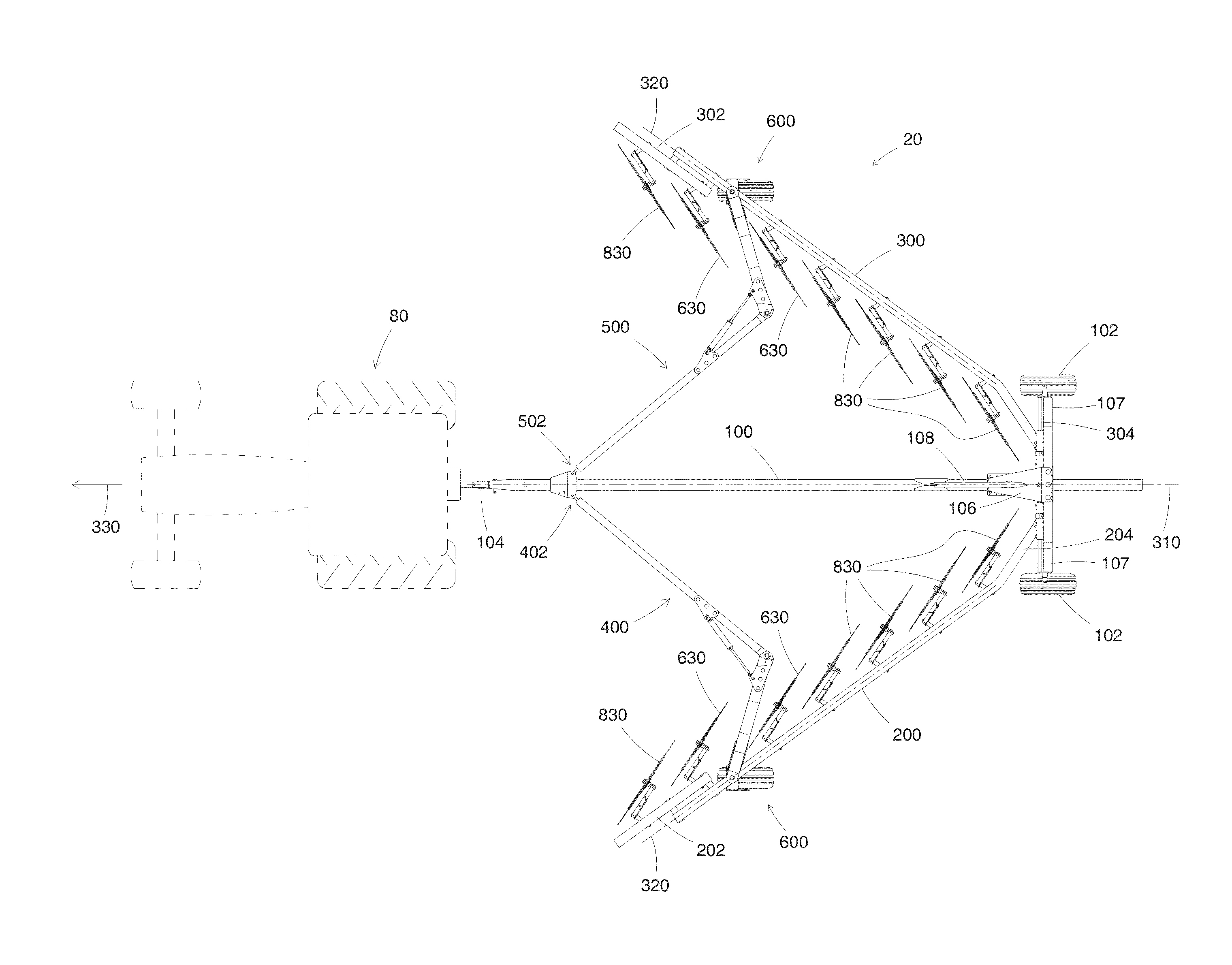
[0055]Referring now to the drawings wherein like reference numerals indicate identical or corresponding parts throughout the several views, the implement 20 of the present invention is shown in FIG. 3, including a plurality of rake wheels 630, 830 operatively, rotatably attached to a left toolbar 200 and a right toolbar 300. The implement 20 is depicted in the operational position and towed by a tractor 80 in FIG. 3. In FIG. 4, the same implement 20 is depicted in a transport position and towed by the tractor 80.

[0056]An elongated tongue member 100 is shown in FIGS. 3, 4 and 7, operatively attached at a front end to a hitch structure 22 while at a rear end the elongated tongue member 100 is disposed in and extends through a slide box 106. The slide box 106 is operatively, rigidly attached to a frame 107. The frame 107 comprises downwardly depending portions for rotatably mounting ground-engaging transport wheels 102.

[0057]The tongue includes a hitch 104. The hitch 104 is supported b...


PUM


Abstract

A folding frame for an agricultural implement such as a wheel rake. The frame includes ground engaging wheels and two toolbars foldable for operation and for transport. The folding frame is provided flexibility to conform to uneven surfaces, yet stability against the torques and forces of operation. A slidable tongue provides folding action between the transport position and the operating position. A spacing between rear ends of the two toolbars may be altered hydraulically for wider or narrower windrows. A novel caster wheel provides support for the toolbars and is located so that the implement's transport position is narrower than the prior art's.

Description

CROSS REFERENCE TO RELATED APPLICATIONS[0001]This is a Continuation-in-Part of U.S. patent application Ser. No. 12 / 482,567, filed Jun. 11, 2009, now U.S. Pat. No. 8,267,186 and which also claims benefit of U.S. Ser. No. 61 / 313,398, filed Mar. 12, 2010.[0002]Priority is claimed from both of the above identified applications and both are incorporated herein by reference in their entirety.STATEMENT REGARDING FEDERALLY SPONSORED RESEARCH OR DEVELOPMENT[0003]Not applicable.REFERENCE TO MICROFICHE APPENDIX[0004]Not applicable.BACKGROUND OF THE INVENTION[0005]1. Field of the Invention[0006]The present invention relates generally to an agricultural implement including a folding toolbar. More particularly, the present invention relates to an improved method and apparatus for providing stability for the folding toolbar as well as flexibility when operating on uneven terrain.[0007]2. Background Art[0008]As farm implements are made to cover greater areas in a single pass, components of those im...

Claims


Application Information

Patent Timeline
Patent Type & Authority Patents(United States)
IPC IPC(8): A01B49/00
CPCA01B73/067A01D78/146
Inventor THOMPSON, KENT L.VASKE, MICHAEL R.BENTZINGER, RUSTIN V.KINDLEY, MICHAEL
Owner VERMEER MFG CO
Why Eureka
Try Eureka