Method and system for reversibly controlled drilling of luminal occlusions

a luminal occlusion, controlled technology, applied in the field of medical methods and systems, can solve the problems of difficulty for users to pull back or advance, fracture and/or fatigue, and reach a level

Active Publication Date: 2014-02-25
BOSTON SCI SCIMED INC
View PDF172 Cites 800 Cited by
  • Summary
  • Abstract
  • Description
  • Claims
  • Application Information

AI Technical Summary

Benefits of technology

[0021]The elongate member of the drilling device typically comprises a tube, such as a hypotube, having a diameter in the range from 0.008 in. to 0.04 in. typically from 0.009 in. to 0.035 in. In some embodiments, the motor will be fixedly connected to the drive shaft, while in other embodiments the motor may be detached from the drive shaft. In most embodiments, the drill tip will have a symmetric or other design which allows the drill tip to penetrate equally well in both rotational directions.

Problems solved by technology

If the rotational direction is not reversed, excessive loose tissue wrapping may cause the rotating tip to become trapped and make it difficult for the user to pull back or advance.
If the rotational direction is not reversed the torque would reach a level causing fracture and / or fatigue.

Method used


Image

  • Method and system for reversibly controlled drilling of luminal occlusions
  • Method and system for reversibly controlled drilling of luminal occlusions
  • Method and system for reversibly controlled drilling of luminal occlusions

Examples


Embodiment Construction

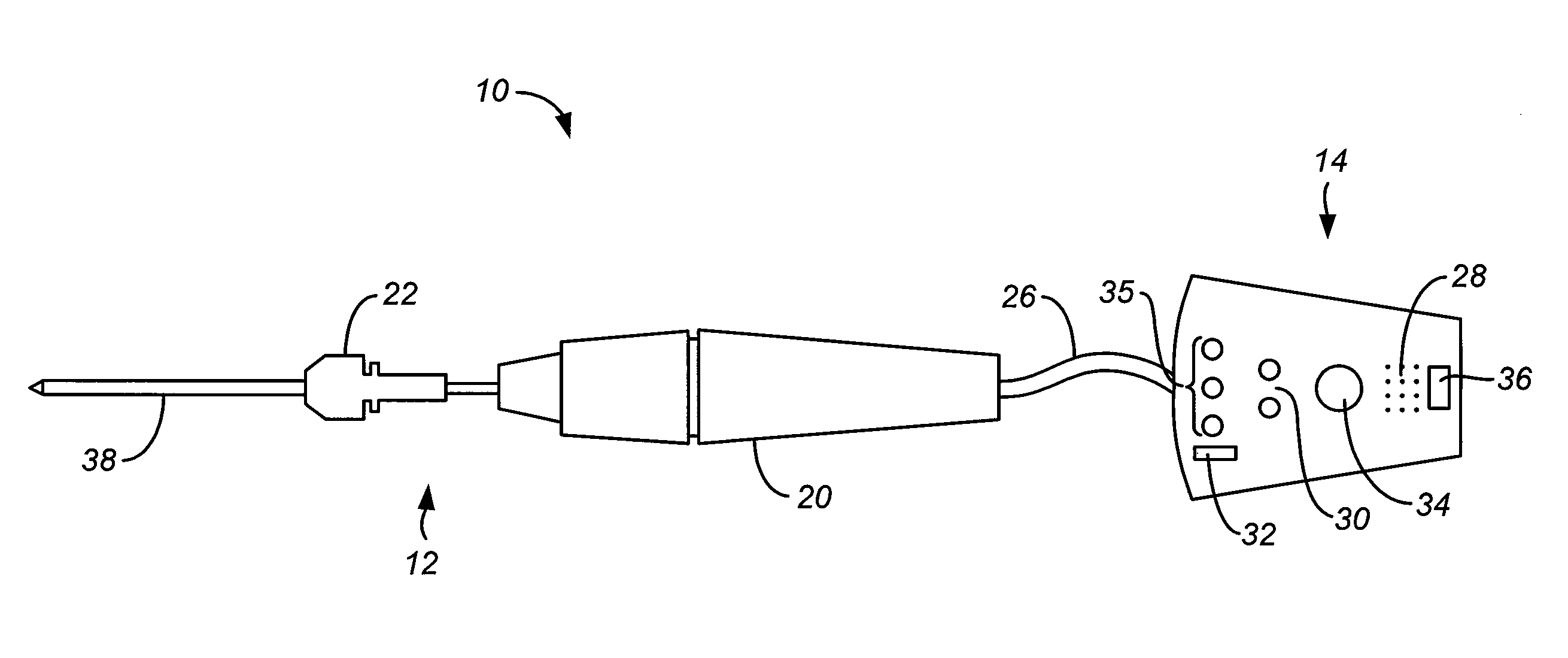
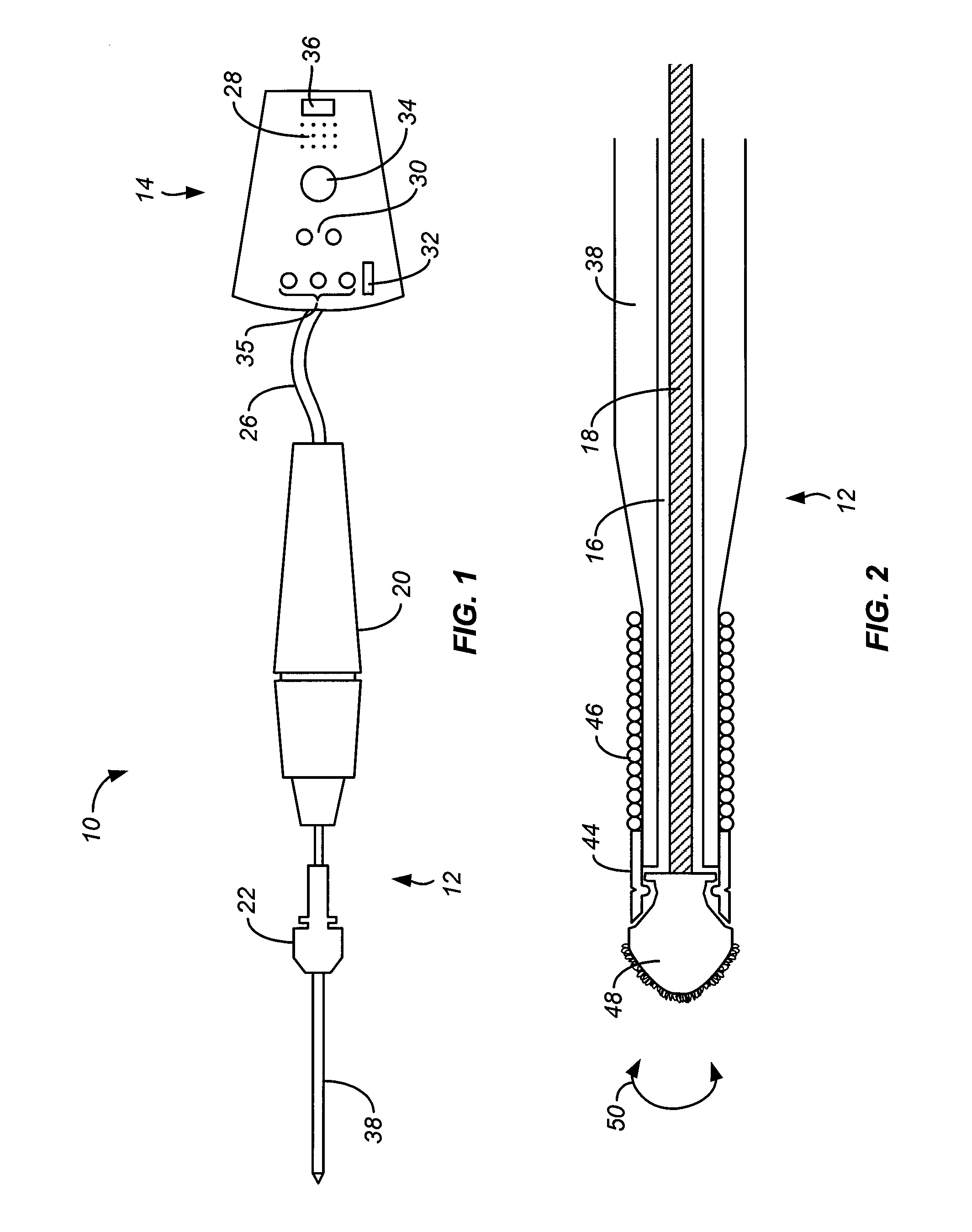
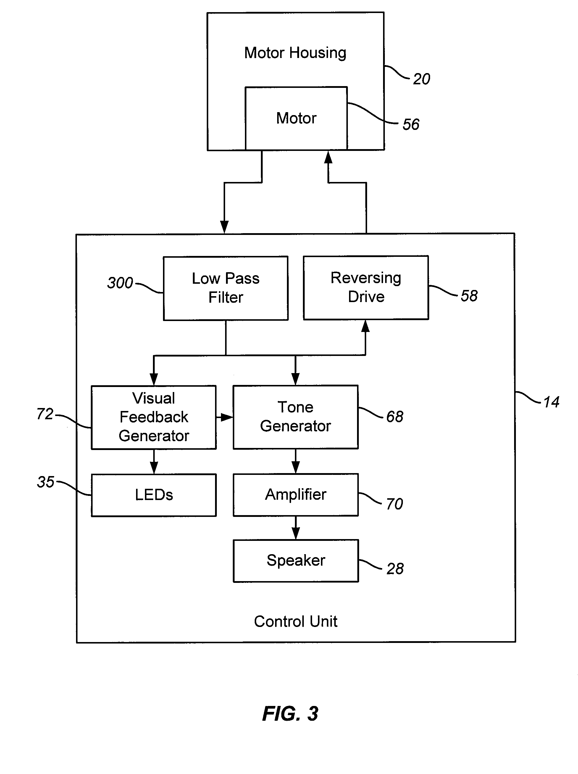
[0031]Referring now to FIG. 1, an exemplary luminal drilling system 10 constructed in accordance with the principles of the present invention is illustrated. The system 10 includes a drilling device 12 configured to cross an occlusion and a control unit 14. The drilling device 12 includes an elongate flexible member 38 having an axial lumen 16 and a drive shaft 18 extending through the axial lumen 16, as best shown in FIG. 2. An adjustable torquer 22 is placed over the elongate flexible member 38. The adjustable torquer 22 may be axially moved along the elongate flexible member 38 and locked down anywhere along the length of the elongate flexible member 38. A motor housing 20 is coupled to a proximal end of the device 12. The control unit 14 is coupled to the motor housing 20 via wire leads or cables 26. The motor housing 20 includes a motor 56 (FIG. 3) to rotationally oscillate the drive member. The control unit 14 includes control circuitry for reversing the direction of rotation,...


PUM

PropertyMeasurementUnit
widthaaaaaaaaaa
widthaaaaaaaaaa
widthaaaaaaaaaa

Abstract

A luminal drilling system includes a drilling device and a control unit. The drilling device includes an elongate member having a drive shaft with a drill tip. The control unit includes a motor connectable to the drive shaft and control circuitry which rotationally oscillates the drive shaft with the direction of rotation automatically reversing whenever the load on the motor and / or drive shaft exceeds a threshold value.

Description

CROSS-REFERENCES TO RELATED APPLICATIONS[0001]The present application is related to but does not claim priority from application Ser. No. 11 / 388,251, filed on Mar. 22, 2006, and application Ser. No. 11 / 636,388, filed on Dec. 7, 2006, the full disclosures of which are incorporated herein by reference.BACKGROUND OF THE INVENTION[0002]1. Field of the Invention[0003]The present invention relates generally to medical methods and systems. More particularly, the present invention relates to a method and driver for the controlled, reversible drilling of an occlusion in a body lumen, such as a calcific occlusion in a blood vessel.[0004]Cardiovascular disease frequently arises from the accumulation of atheromatous material on the inner walls of vascular lumens, particularly arterial lumens of the coronary and other vasculature, resulting in a condition known as atherosclerosis. Atheromatous and other vascular deposits restrict blood flow and can cause ischemia which, in acute cases, can resul...

Claims


Application Information

Patent Timeline
Patent Type & Authority Patents(United States)
IPC IPC(8): A61B17/00
CPCA61B2017/00128A61B17/320758A61B2019/464A61B2017/00398A61B2017/00115A61B2090/064Y10T408/03
Inventor PALERMO, THOMAS
Owner BOSTON SCI SCIMED INC
Why Eureka
Try Eureka