Multilayer capacitor having reduced equivalent series inductance

a multi-layer capacitor and equivalent series technology, applied in the field of multi-layer capacitors, can solve the problems of further reduction in esl and inability to achieve esl reduction effect, and achieve the effects of reducing esl, improving reliability of multi-layer capacitors, and reducing esl

Active Publication Date: 2014-02-25
TDK CORPARATION
View PDF23 Cites 8 Cited by
  • Summary
  • Abstract
  • Description
  • Claims
  • Application Information

AI Technical Summary

Benefits of technology

[0006]The invention has been finalized in order to solve the above problems, and an object of the invention is to provide a multilayer capacitor capable of improving reliability and further reducing ESL.
[0008]In this multilayer capacitor, the first lead portion respectively connects the second principal-surface electrode portion and the first lateral portion of the first terminal electrode, and the second lead portion respectively connects the fifth principal-surface electrode portion and the second lateral portion of the second terminal electrode. In this way, the first lead portion and the second lead portion having different polarities are led to the same lateral surface of the element body, and the lateral portions are formed at the lateral surfaces of each terminal electrode. Thus, the inter-lead-electrode distance between the first lead portion and the second lead portion having different polarities is shortened compared to a case where the internal electrode is simply led from the end surface of the element body. That is, a current path can be shortened, reducing the ESL. Each lead portion is led to the lateral surface of the element body, reducing variations in the ESL depending on the mounting direction. In the width direction, the second principal-surface electrode portion is greater than the first principal-surface electrode portion, and the fifth principal-surface electrode portion is greater than the fourth principal-surface electrode portion. When viewed from the lamination direction, the outer edge of second principal-surface electrode portion at the other end side is arranged near the other end side more than the outer edge side of the fifth principal-surface electrode portion at the one end side, or arranged to be aligned with the outer edge of the fifth principal-surface electrode portion at the one end side. The first lead portion is connected to the second principal-surface electrode portion, and the second lead portion is connected to the fifth principal-surface electrode portion. Thus, portions of the second principal-surface electrode portion greater than the first principal-surface electrode portion and portions of the fifth principal-surface electrode portion greater than the fourth principal-surface electrode portion function as current path between the first lead portion and the second lead portion, making it possible to shorten the current path. Therefore, the reliability can be improved, and the ESL can be further reduced.
[0009]In the multilayer capacitor according to the invention, in the longitudinal direction of the first internal electrode and the second internal electrode, the outer edge of the second principal-surface electrode portion at the other end side of the element body may extend to the second lead portion, and the outer edge of the fifth principal-surface electrode portion at the one end side of the element body may extend to the first lead portion. Therefore, the current path (for example, EL1 and EL2 of FIGS. 6A and 6B) can be ensured reliably, and the ESL can be reduced.
[0010]The first lead portion may has a first small-width portion extending from the second principal-surface electrode portion in the width direction and a first connection portion extending toward the one end side of the element body at portion where connection is made to the first lateral portion of the first terminal electrode. The second lead portion may has a second small-width portion extending from the fifth principal-surface electrode portion in the width direction and a second connection portion extending toward the other end side of the element body at portion where connection is made to the second lateral portion of the second terminal electrode. With this configuration, since the small-width portion is arranged inside the element body more than the connection portion, the current path can be shortened, and the ESL can be made low. In addition, since the connection portions are formed, connectivity to the terminal electrode can be ensured. The surfaces of the dielectric layers are exposed between the small-width portions and the connection portions, increasing the exposed area of the dielectric layer. A portion where the dielectric layer is exposed is rigidly fixed to the rear surface of the overlying dielectric layer at the time of calcination. Therefore, adhesiveness of the element body 1 can be improved. With the small-width portions, the ESL can be adjusted.
[0011]The first internal electrode may have a first additional lead portion connected to the first end portion of the first terminal electrode, and the second internal electrode may have a second additional lead portion connected to the second end portion of the second terminal electrode. With an increase in the number of lead portions, the ESL can be further reduced.
[0013]According to the aspect of the invention, reliability can be improved and the ESL can be further reduced.

Problems solved by technology

However, in the above-described multilayer capacitor, the ESL reduction effect is insufficient, and there is demand for further reduction in the ESL.
In the configuration such that the internal electrode is simply brought close to the mounting surface, in mounting the substrate, if the substrate is not mounted in an appropriate mounting direction, the ESL reduction effect is not obtained, and there is a problem with availability.

Method used


Image

  • Multilayer capacitor having reduced equivalent series inductance
  • Multilayer capacitor having reduced equivalent series inductance
  • Multilayer capacitor having reduced equivalent series inductance

Examples


first embodiment

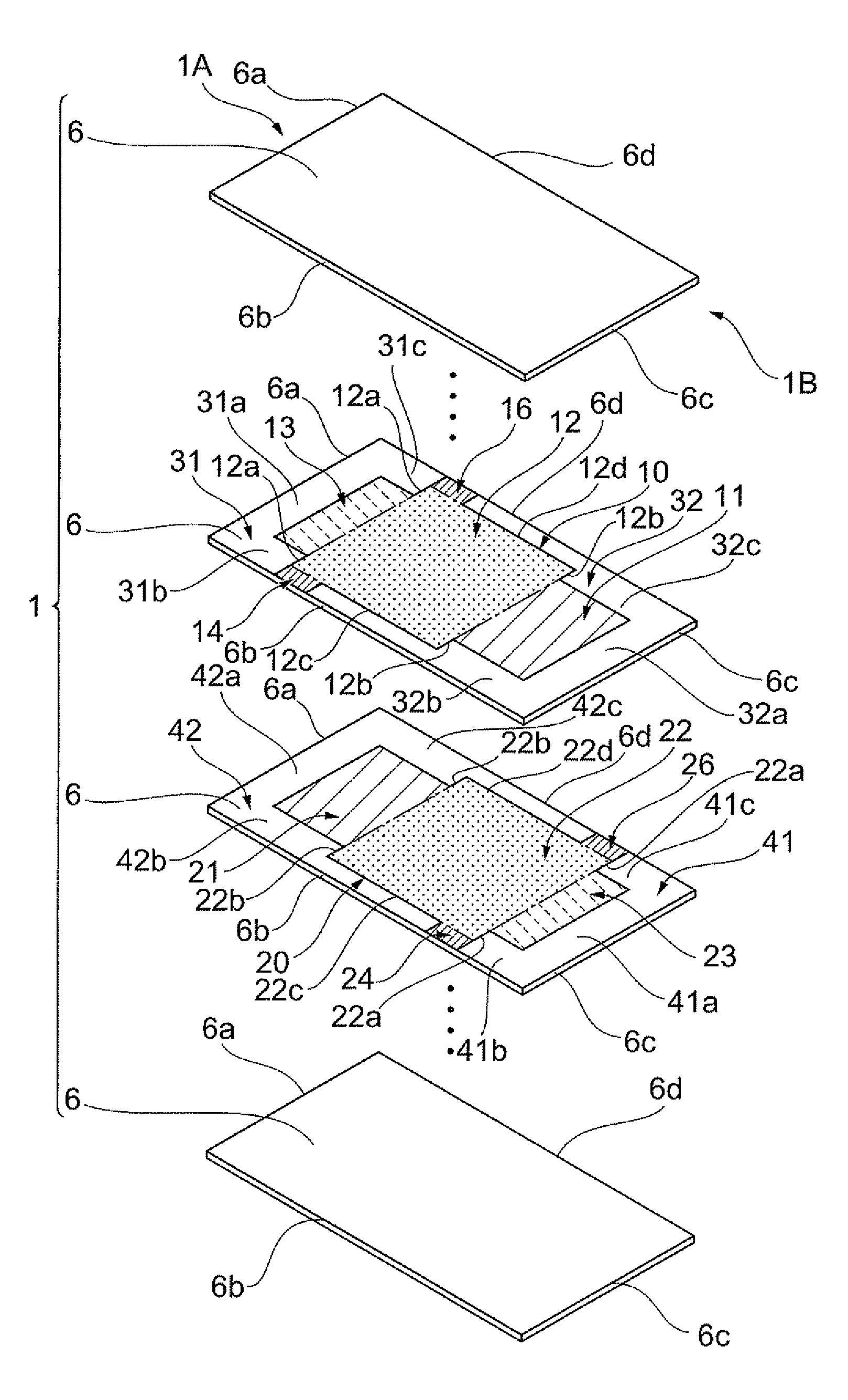
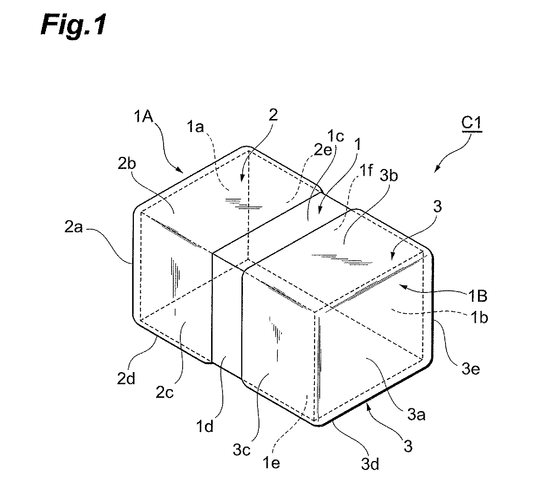
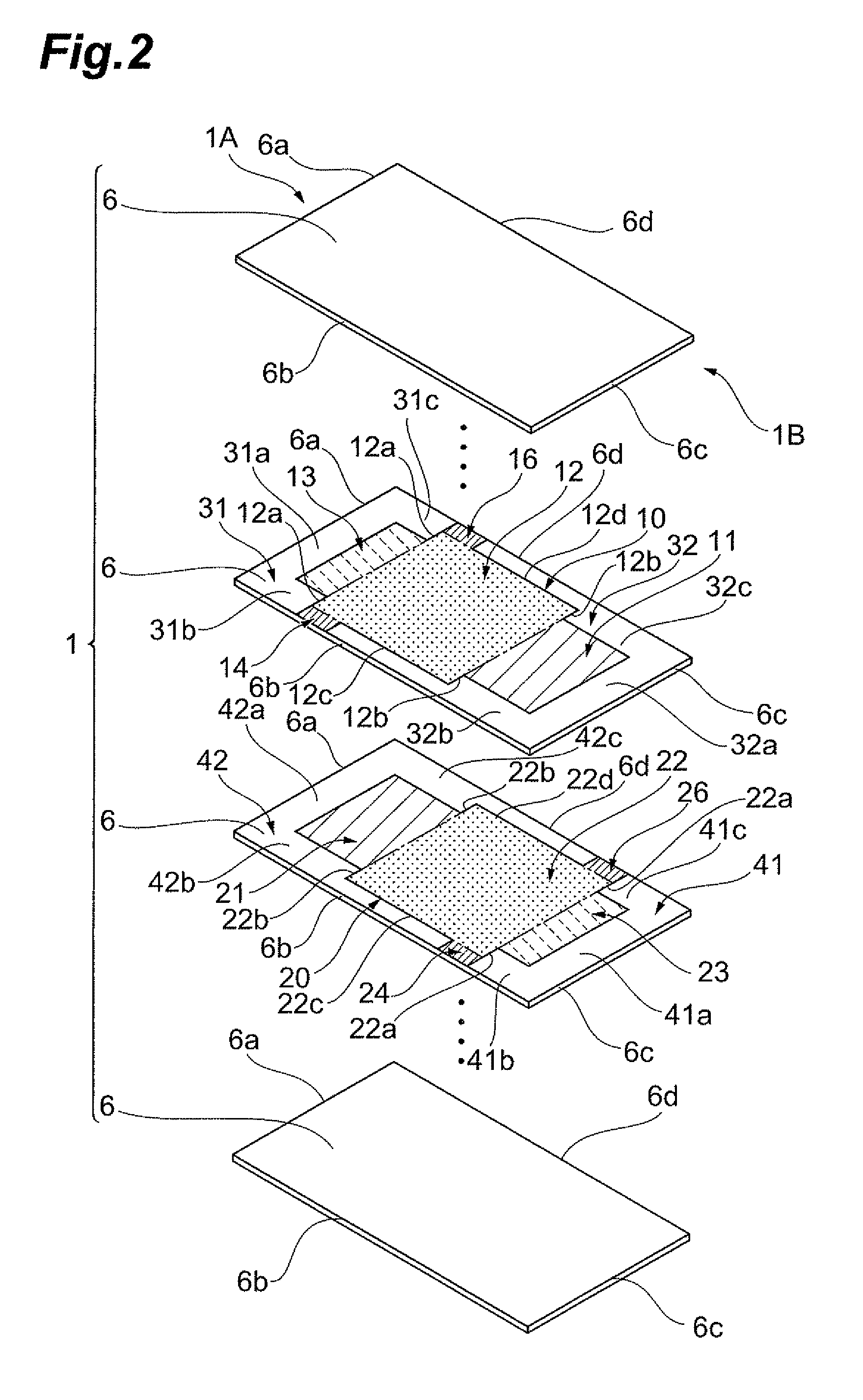
[0026]The configuration of a multilayer capacitor C1 according to a first embodiment will be described with reference to FIGS. 1 to 3B. FIG. 1 is a perspective view showing the multilayer capacitor C1 according to the first embodiment. FIG. 2 is an exploded view of an element body when exploded by dielectric layer. FIGS. 3A and 3B are diagrams of a first internal electrode and a second internal electrode when viewed from a lamination direction. In FIG. 3A, a solid line indicates the first internal electrode, and a virtual line indicates the second internal electrode. In FIG. 3B, a solid line indicates the second internal electrode, and a virtual line indicates the first internal electrode. As shown in FIG. 1, the multilayer capacitor C1 includes an element body 1 which is constituted to have a substantially rectangular parallelepiped having a plurality of rectangular plate-shaped dielectric layers laminated as a single body, and a first terminal electrode 2 and a second terminal ele...

second embodiment

[0044]A multilayer capacitor according to a second embodiment will be described with reference to FIGS. 5A and 5B. FIGS. 5A and 5B are diagrams of a first internal electrode and a second internal electrode of the multilayer capacitor according to the second embodiment when viewed from the lamination direction. The multilayer capacitor according to the second embodiment is mainly different from the multilayer capacitor according to the first embodiment in that a second principal-surface electrode portion 312 of a first internal electrode 310 and a fifth principal-surface electrode portion 322 of a second internal electrode 320 have a short length in the longitudinal direction.

[0045]While an outer edge 312a of the second principal-surface electrode portion 312 is arranged near the one end 1A side, an outer edge 312b of the second principal-surface electrode portion 312 of the first internal electrode 310 at the other end 1B side is arranged at the center position of the element body 1...

third embodiment

[0046]A multilayer capacitor according to a third embodiment will be described with reference to FIGS. 6A and 6B. FIGS. 6A and 6B are diagrams of a first internal electrode and a second internal electrode of the multilayer capacitor according to the third embodiment when viewed from the lamination direction. The multilayer capacitor according to the third embodiment is different from the multilayer capacitor according to the first embodiment in that, in the longitudinal direction, the outer edge of a second principal-surface electrode portion at the other end 1B side extends to the second lead portions, and the outer edge of a fifth principal-surface electrode portion at the one end 1A side of the element body extends to first lead portions.

[0047]Specifically, an outer edge 412b of a second principal-surface electrode portion 412 of a first internal electrode 410 at the other end 1B side is aligned with an outer edge 422a of a fifth principal-surface electrode portion 422 of a secon...


PUM


Abstract

A multilayer capacitor is provided with improved reliability and reduced ESL. In a width direction, a second principal-surface electrode portion is greater than a first principal-surface electrode portion, and a fifth principal-surface electrode portion is greater than a fourth principal-surface electrode portion. When viewed from a lamination direction, an outer edge of the second principal-surface electrode portion at the other end side is arranged near the other end side more than outer edge of the fifth principal-surface electrode portion at one end side. First lead portions are connected to the second principal-surface electrode portion, and second lead portions are connected to the fifth principal-surface electrode portion. Thus, portions of the second principal-surface electrode portion greater than the first principal-surface electrode portion and portions of the fifth principal-surface electrode portion greater than the fourth principal-surface electrode portion function as current paths between the first lead portions and the second lead portions.

Description

BACKGROUND OF THE INVENTION[0001]1. Field of the Invention[0002]The present invention relates to a multilayer capacitor.[0003]2. Related Background Art[0004]A multilayer capacitor is known which includes an element body formed by laminating a plurality of dielectric layers, a pair of terminal electrodes formed at both end portions of the element body, a first internal electrode formed inside the element body to extend from one end surface of the element body and connected one terminal electrode, and a second internal electrode formed inside the element body to extend from the other end surface of the element body and connected to the other terminal electrode (for example, see Japanese Utility Model Application Laid-Open No. 62-124836).SUMMARY OF THE INVENTION[0005]In general, a multilayer capacitor has ESL (Equivalent Series Inductance) which is a minute inductance component, and there is demand for reduction in the ESL. The above-described multilayer capacitor is intended to reduce...

Claims


Application Information

Patent Timeline
Patent Type & Authority Patents(United States)
IPC IPC(8): H01G4/005H01G4/228H01G4/06
CPCH01G4/228
Inventor TOGASHI, MASAAKIHASEBE, KAZUYUKI
Owner TDK CORPARATION
Why Eureka
Try Eureka