Electrical door-locking device

a technology of electric door locks and door locks, which is applied in the direction of door/window fittings, wing accessories, lock applications, etc., can solve the problems of increased fabrication and maintenance costs, dangerous situations, etc., and achieves the effect of reducing the danger of failure and operation errors, simple structure, and convenient fabrication and maintenan

Inactive Publication Date: 2014-03-04
THE KOREA DEV BANK
View PDF51 Cites 13 Cited by
  • Summary
  • Abstract
  • Description
  • Claims
  • Application Information

AI Technical Summary

Benefits of technology

[0009]Accordingly, the present invention has been made keeping in mind the above problems occurring in the related art, and the present invention is intended to propose to an electric door lock which has a simple structure, ensures the reliability of a locking function, reduces a danger of a failure and an operation error, and is easy to fabricate and maintain, saving the cost for the fabrication and maintenance relative to the cost taken in the related art, and an electric door having the same.Solution to Problem
[0024]As set forth before, the electric door lock has a simple structure, ensures the reliability of a locking function, reduces a danger of a failure and an operation error, and is easy to fabricate and maintain, saving the cost for the fabrication and maintenance relative to the cost taken in the related art.

Problems solved by technology

However, if the situation is that the railway train is running, or the state of the railway tracks is dangerous, or otherwise if nevertheless the situation is not an emergency state, the passengers can open the electric door even with their less effort, a very dangerous situation can be caused.
However, the conventional electric door lock having the above-mentioned configuration has a problem of increased cost of fabrication and maintenance because of numerous, complex parts.

Method used


Image

  • Electrical door-locking device
  • Electrical door-locking device
  • Electrical door-locking device

Examples


Embodiment Construction

[0036]Reference will now be made in greater detail to a preferred embodiment of the invention, an example of which is illustrated in the accompanying drawings. Wherever possible, the same reference numerals will be used throughout the drawings and the description to refer to the same or like parts.

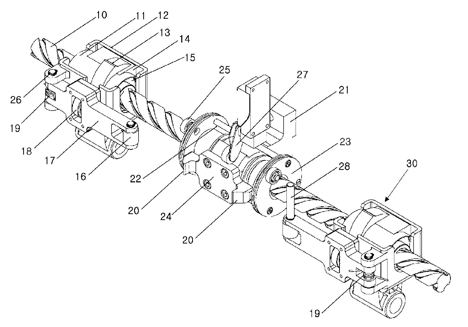
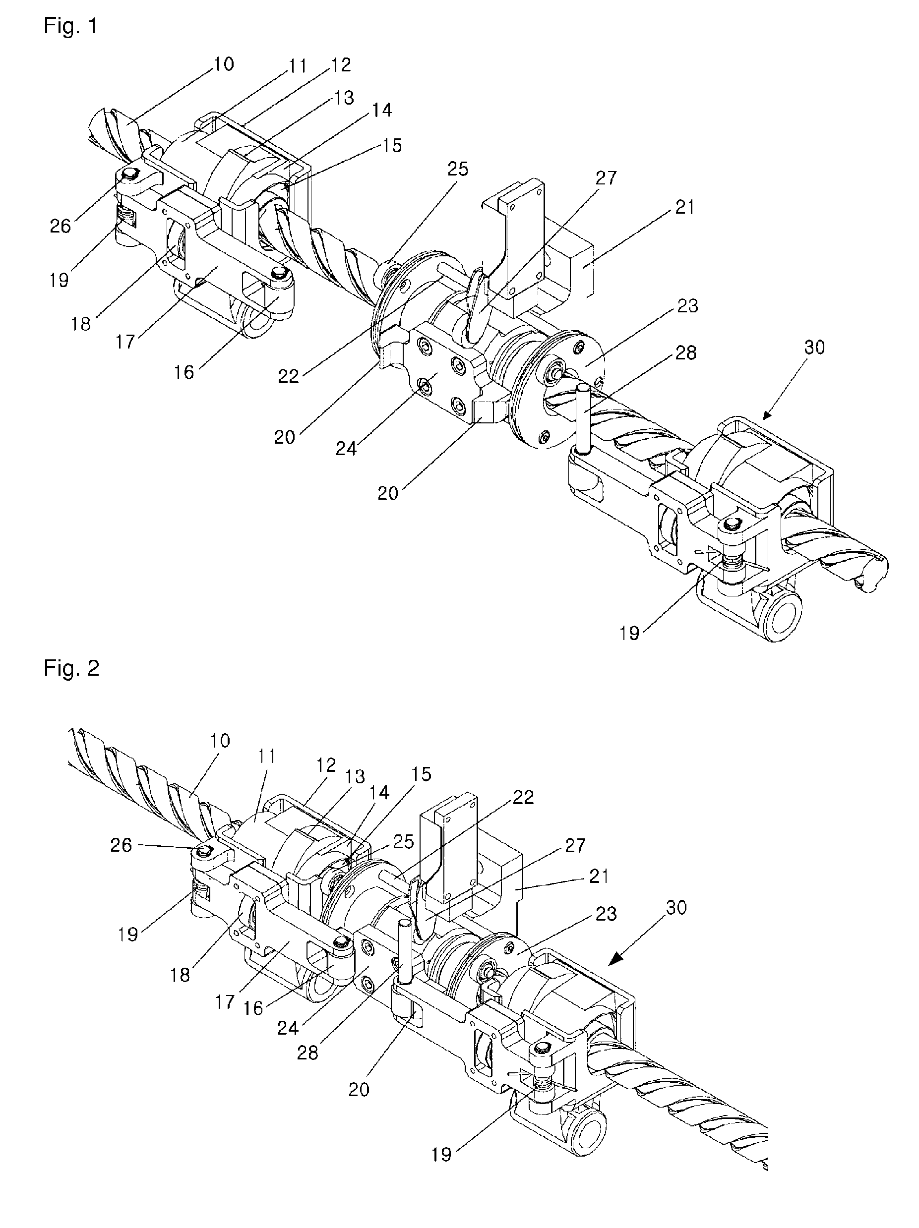
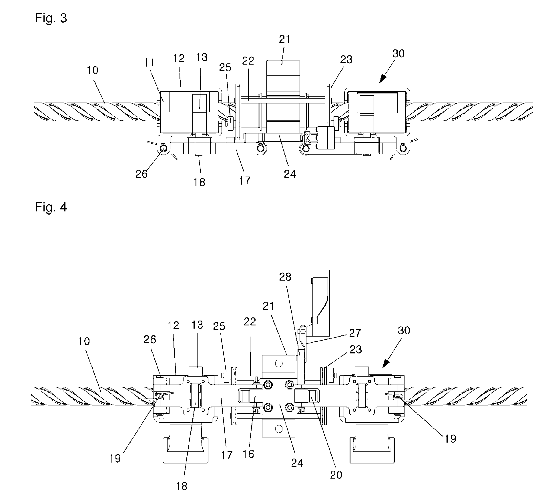
[0037]FIG. 1 is a perspective view showing an electric door lock according to an embodiment of the present invention when it is being closed, FIG. 2 is a perspective view showing the electric door lock according to an embodiment of the present invention when it was completely closed, FIG. 3 is a plan view showing the electric door lock of FIG. 2 which was closed, and FIG. 4 is a front view showing the electric door lock of FIG. 2 which was closed.

[0038]FIG. 5 is a perspective view showing an electric door lock according to an embodiment of the present invention when it starts opening, FIG. 6 is a perspective view showing an electric door lock according to an embodiment of the present inven...


PUM


Abstract

An electrical door-locking device includes screws which are rotatable in a forwards and backwards direction, and are placed in line on one side of a door frame in the direction in which the electrical door main body slides; locking hooks located adjacent to the screws; and a sliding unit equipped with a rotatably-provided locking lever having a latch for latching onto the locking hooks when the electrical door main body is closed and is equipped with a locking-lever-pressing part for pressing the locking lever such that the latch of the locking lever unlatches from the locking hooks, and one end of which is rotatably linked to the screws and the other end of which is linked to the electrical door main body.

Description

CROSS REFERENCE TO RELATED APPLICATION[0001]This application claims the priority of Korean Patent Application No. 10-2009-0028373, filed on Apr. 2, 2009 in the KIPO (Korean Intellectual Property Office), the disclosure of which is incorporated herein in their entirety by reference. Further, this application is the National Phase application of International Application No. PCT / KR2010 / 002027, filed on Apr. 1, 2010, which designates the United States and was published in Korean. Each of these applications is hereby incorporated by reference in their entirety into the present application.FIELD OF THE INVENTION[0002]The present invention relates, in general, to an electric door lock and an electric door having the same and, more particularly, to an electric door lock which has a simple structure, ensures the reliability of a locking function, reduces a danger of a failure and an operation error, and is easy to fabricate and maintain, saving the cost for the fabrication and maintenance r...

Claims


Application Information

Patent Timeline
Patent Type & Authority Patents(United States)
IPC IPC(8): E06B3/70E05B47/00E05B65/08
CPCE05B2047/0023E05B83/02E05B47/0012E05F15/652E05B83/363E05Y2201/22E05Y2201/232Y10T70/5155Y10T70/7062E05B2047/0086
Inventor LEE, CHUL
Owner THE KOREA DEV BANK
Why Eureka
Try Eureka